
H3C S7500E Series Ethernet Switches Operation Manual

Operation Manual – VLAN
H3C S7500E Series Ethernet Switches Chapter 1 VLAN Configuration
1-15
z This port allows packets from VLAN 2, VLAN 6 to VLAN 50, and VLAN 100 to pass
through.
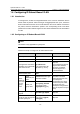
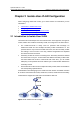
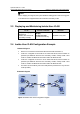
II. Network diagram
Figure 1-4 Network diagram for port-based VLAN configuration
III. Configuration procedure
1) Configure Device A
# Create VLAN 2, VLAN 6 through VLAN 50, and VLAN 100.
<DeviceA> system-view
[DeviceA] vlan 2
[DeviceA-vlan2] quit
[DeviceA] vlan 100
[DeviceA-vlan100] vlan 6 to 50
Please wait... Done.
# Enter Ethernet 2/0/1 port view.
[DeviceA] interface Ethernet 2/0/1
# Configure Ethernet 2/0/1 as a Trunk port and configure its default VLAN ID as 100.
[DeviceA-Ethernet2/0/1] port link-type trunk
[DeviceA-Ethernet2/0/1] port trunk pvid vlan 100
# Configure Ethernet 2/0/1 to deny the packets of VLAN 1 (by default, the packets of
VLAN 1 are permitted on all the ports).
[DeviceA-Ethernet2/0/1] undo port trunk permit vlan 1
# Configure packets from VLAN 2, VLAN 6 through VLAN 50, and VLAN 100 to pass
through Ethernet 2/0/1.
[DeviceA-Ethernet2/0/1] port trunk permit vlan 2 6 to 50 100
Please wait... Done.
2) # Configure Device B following similar steps as that of Device A.
IV. Verification
Verifying the configuration of Device A is similar to that of Device B. so only Device A is
taken for example here.
# Display the information about Ethernet 2/0/1 of Device A to verify the above
configurations.
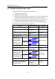
<DeviceA> display interface ethernet 2/0/1
Ethernet2/0/1 current state: UP