
H3C S7500E Series Ethernet Switches Operation Manual

Operation Manual – DHCP
H3C S7500E Series Ethernet Switches Chapter 3 DHCP Relay Agent Configuration
3-10
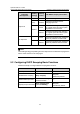
To do… Use the command… Remarks
Display information about
the configuration of a
specified or all DHCP server
groups
display dhcp relay
server-group { group-id |
all }
Available in any view
Display packet statistics on
relay agent
display dhcp relay
statistics [ server-group
{ group-id | all } ]
Available in user
view
Clear packet statistics from
relay agent
reset dhcp relay statistics
[ server-group group-id ]
Available in user
view
3.5 DHCP Relay Agent Configuration Example
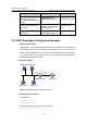
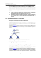
I. Network requirements
VLAN-interface 1 on the DHCP relay agent (Switch A) connects to the network where
DHCP clients reside. The IP address of VLAN-interface 1 is 10.10.1.1/24 and IP
address of VLAN-interface 2 is 10.1.1.2/24 that communicates with the DHCP server
10.1.1.1/24. As shown in the figure below, Switch A forwards messages between
DHCP clients and the DHCP server.
II. Network diagram
Switch B
DHCP server
Switch A
DHCP relay agent
DHCP client DHCP client
DHCP clientDHCP client
Vlan-int2
10.1.1.2/24
Vlan-int1
10.10.1.1/24
Vlan-int2
10.1.1.1/24
Figure 3-3 Network diagram for DHCP relay agent
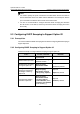
III. Configuration procedure
# Enable DHCP.
<SwitchA> system-view
[SwitchA] dhcp enable
# Enable the DHCP relay agent on VLAN-interface 1.
[SwitchA] interface vlan-interface 1