
H3C S7500E Series Ethernet Switches Operation Manual

Operation Manual – VLAN
H3C S7500E Series Ethernet Switches Chapter 2 Isolate-User-VLAN Configuration
2-1
Chapter 2 Isolate-User-VLAN Configuration
When configuring Isolate-user VLAN, go to these sections for information you are
interested in:
z Introduction to Isolate-User-VLAN
z Configuring Isolate-User-VLAN
z Displaying and Maintaining Isolate-User-VLAN
z Isolate-User-VLAN Configuration Example
2.1 Introduction to Isolate-User-VLAN
The isolate-user-VLAN adopts a two-tier VLAN structure. In this approach, two types of
VLANs, isolate-user-VLAN and secondary VLAN, are configured on the same device.
z The isolate-user-VLAN is mainly used for upstream data exchange. An
isolate-user-VLAN can have multiple secondary VLANs associated to it. The
upstream device only knows the isolate-user-VLAN, how the secondary VLANs
are working is not its concern. In this way, network configurations are simplified
and VLAN resources are saved.
z Secondary VLANs are used for connecting users. Secondary VLANs are isolated
from each other on Layer 2. To allow users from different secondary VLANs under
the same isolate-user-VLAN to communicate with each other, you can enable
ARP proxy on the upstream device to realize Layer 3 communication between the
secondary VLANs.
z One isolate-user-VLAN can have multiple secondary VLANs, which are invisible to
the corresponding upstream device.
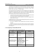
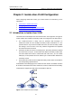
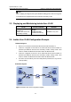
As illustrated in the following figure, the isolate-user-vlan function is enabled on Switch
B. VLAN 10 is the isolate-user-VLAN, and VLAN 2, VLAN 5, and VLAN 8 are secondary
VLANs that are mapped to VLAN 10 and are invisible to Switch A.
Figure 2-1 An isolate-user-vlan example