
H3C S7500E Series Ethernet Switches Operation Manual

Operation Manual – VLAN
H3C S7500E Series Ethernet Switches Chapter 2 Isolate-User-VLAN Configuration
2-3
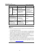
Note:
After a mapping is configured, the system disallows adding ports to and removing ports
or VLANs from the mapped isolate-user-VLAN and secondary VLAN.
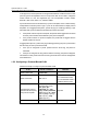
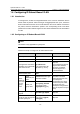
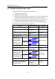
2.3 Displaying and Maintaining Isolate-User-VLAN
To do... Use the command... Remarks
Display the mapping
between an
isolate-user-vlan and its
secondary VLAN(s)
display
isolate-user-vlan
[ isolate-user-vlan-id ]
Available in any view
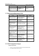
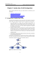
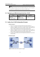
2.4 Isolate-User-VLAN Configuration Example
I. Network diagram
z Device A is connected to downstream devices Device B and Device C;
z VLAN 5 is configured on Device B as an isolate-user-VLAN, which includes an
upstream port Ethernet 2/0/5 and two secondary VLANs, namely VLAN 2 and
VLAN 3. VLAN 2 has Ethernet 2/0/2 and VLAN 3 has Ethernet 2/0/1.
z VLAN 6 is configured on Device C as an isolate-user-VLAN, which includes an
upstream port Ethernet 2/0/5 and two secondary VLANs, namely VLAN 3 and
VLAN 4. VLAN 3 has Ethernet 2/0/3 and VLAN 4 has Ethernet 2/0/4.
z For Device A, Device B only has one VLAN (VLAN 5) and Device C only has one
VLAN (VLAN 6).
II. Network diagram
Figure 2-2 Isolate-User-VLAN configuration diagram