H3C S7502 Ethernet Switch Installation Manual Hangzhou H3C Technologies Co., Ltd. http://www.h3c.com Manual Version: T2-08046H-20071205-C-1.
Copyright © 2006-2007, Hangzhou H3C Technologies Co., Ltd. All Rights Reserved No part of this manual may be reproduced or transmitted in any form or by any means without prior written consent of Hangzhou H3C Technologies Co., Ltd. Trademarks H3C, , Aolynk, , H3Care, , TOP G, , IRF, NetPilot, Neocean, NeoVTL, SecPro, SecPoint, SecEngine, SecPath, Comware, Secware, Storware, NQA, VVG, V2G, VnG, PSPT, XGbus, N-Bus, TiGem, InnoVision and HUASAN are trademarks of Hangzhou H3C Technologies Co., Ltd.
About This Manual Related Documentation In addition to this manual, each H3C S7502 Ethernet Switch documentation set includes the following: Manual Description H3C S7500 Series Ethernet Switches Operation Manual Guides the user to configure the features supported by the S7500 series. H3C S7500 Series Ethernet Switches Command Manual Elaborates on the commands configuring the S7500 series.
Chapter Contents 8. Troubleshooting Introduces how to troubleshoot the configuration system, power system, fans, and LPUs of the H3C S7502 Ethernet Switch. Appendix A Lightning Protection Introduces lightning protection of the H3C S7502 Ethernet switch. Appendix B AC Power Cables Used in Different Countries Introduces the AC power cables used in different countries, including 10A AC power cables and 16A AC power cables. Conventions The manual uses the following conventions: I.
Installation Manual H3C S7502 Ethernet Switch Table of Contents Table of contents Chapter 1 Product Overview ........................................................................................................ 1-1 1.1 General Information ........................................................................................................... 1-1 1.1.1 Preface .................................................................................................................... 1-1 1.1.
Installation Manual H3C S7502 Ethernet Switch Table of Contents 1.11 Physical Description of the S7502 ................................................................................. 1-23 1.11.1 Chassis and Slots ............................................................................................... 1-23 1.11.2 Color Description on the Fan Tray and Cards .................................................... 1-27 1.11.3 Backplane.....................................................................
Installation Manual H3C S7502 Ethernet Switch Chapter 1 Product Overview Chapter 1 Product Overview 1.1 General Information 1.1.1 Preface H3C S7500 Series Ethernet Switches are modular, large-capacity Layer 2/3 Ethernet switches that support wire-speed forwarding. The S7500 series include S7502, S7503, S7506, and S7506R.
Installation Manual H3C S7502 Ethernet Switch Chapter 1 Product Overview 1.1.2 Switching Engine Switching engine (also known as SRPU) is the core of the S7502. Currently, switching engines include the following models: z LS81P12TE: provides four 10/100/1000Base-T ports and twelve 1000Base-X (SFP) ports. z LS81T12PE: provides twelve 10/100/1000Base-T ports and four 1000Base-X (SFP) ports.
Installation Manual H3C S7502 Ethernet Switch Chapter 1 Product Overview Switching capacity Packet forwarding rate Number of VLANs LS81T32P 192 Gbps 144 Mpps 4K 16 K 64 K LS81GT48B 192 Gbps 144 Mpps 4K 16 K 64 K LS81GP48 192 Gbps 144 Mpps 4K 16 K 64 K LS81TGX2 144 Gbps 108 Mpps 4K 16 K 64 K LS81TGX4 192 Gbps 144 Mpps 4K 16 K 64 K Item MAC address table Routing table 1.2 LS81P12TE Figure 1-2 Appearance of an LS81P12TE 1.2.
Installation Manual H3C S7502 Ethernet Switch Chapter 1 Product Overview Item LS81P12TE Ethernet port cable and max transmission distance 100 m (328 ft) over category-5 twisted pair cable z z z z z z Supported standard z z z z z z IEEE 802.3 IEEE 802.3u IEEE 802.3z IEEE 802.3ab IEEE 802.1p IEEE 802.1Q IEEE 802.1D IEEE802.1X IEEE802.1s IEEE802.1w IEEE 802.3x IEEE 802.3ad Note: In this manual, card dimensions refer to those of a card with ejector levers. 1.2.
Installation Manual H3C S7502 Ethernet Switch Chapter 1 Product Overview The status LEDs on an LS81P12TE are described in the following table. Table 1-3 Description of LEDs on the panel of an LS81P12TE LED LINK/ACT Status OFF The link is down or no link is presented. ON The link is active. Blinking Data is being transmitted or received on the port. 1.2.3 Port Cable I.
Installation Manual H3C S7502 Ethernet Switch SFP module SFP-GE-LH70-S M1510-CW SFP-GE-LH70-S M1530-CW SFP-GE-LH70-S M1550-CW SFP-GE-LH70-S M1570-CW SFP-GE-LH70-S M1590-CW Chapter 1 Product Overview Central wavelength Matching cable Maximum transmission distance LC 9 µm/125 µm single mode optical fiber cable 70 km (43 mi) LC 9 µm/125 µm single mode optical fiber cable 70 km (43 mi) LC 9 µm/125 µm single mode optical fiber cable 70 km (43 mi) LC 9 µm/125 µm single mode optical fiber cabl
Installation Manual H3C S7502 Ethernet Switch Chapter 1 Product Overview 1.3.1 Specifications Table 1-5 LS81T12PE specifications Item LS81P12TE CPU MPC8245 300 MHz Boot ROM 512 KB Flash memory 32 MB SDRAM 256 MB Dimensions (H × W x D) 40.1 × 376.7 × 354.5 mm (1.6 × 14.8 × 14 in.
Installation Manual H3C S7502 Ethernet Switch Chapter 1 Product Overview Figure 1-6 LS81T12PE panel (1) (8) (7) (2) (6) (1) Interface number (3) Nut (5) Ejector lever (7) Interface status LED (5) (3) (4) (2) Silkscreen (4) LPU edge (Green) (6) SPF port (Gigabit) (8) Ethernet port (Gigabit) Figure 1-7 LS81T12PE panel The status LEDs on an LS81T12PE are described in Table 1-6.
Installation Manual H3C S7502 Ethernet Switch Chapter 1 Product Overview 1.4 LS81T16P Figure 1-8 Appearance of LS81T16P 1.4.1 Specifications LS81T16P provides the XG high-speed bus and 16 × 10/100/1000Base-T ports and 8 × 1000Base-X (SFP) ports. Table 1-7 LS81T16P specifications Item LS81T16P CPU MPC8245 300 MHz BootROM 512 KB Flash memory 32 MB SDRAM 256 MB Dimensions (H × W x D) 40.1 × 376.7 × 354.5 mm (1.6 × 14.8 × 14 in.
Installation Manual H3C S7502 Ethernet Switch Chapter 1 Product Overview Item LS81T16P z z z z z z Supported standard z z z z z z IEEE 802.3 IEEE 802.3u IEEE 802.3z IEEE 802.3ab IEEE 802.1p IEEE 802.1Q IEEE 802.1D IEEE 802.1X IEEE 802.1s IEEE 802.1w IEEE 802.3x IEEE 802.3ad 1.4.2 Panel and LEDs The following figure illustrates the panel of an LS81T16P.
Installation Manual H3C S7502 Ethernet Switch Chapter 1 Product Overview Table 1-8 Description of LEDs on the panel of an LS81T16P LED LINK/ACT Status OFF The link is down or no link is presented. ON The link is active. Blinking Data is being transmitted or received on the port. 1.4.3 Port Cable Refer to section 1.2.3 "Port Cable” on page 1-5 for information about the port cable required by an LS81T16P. 1.5 LS81T32P Figure 1-11 Appearance of LS81T32P 1.5.
Installation Manual H3C S7502 Ethernet Switch Chapter 1 Product Overview Item LS81T32P z z Port rate z z 10 Mbps half/full duplex 100 Mbps half/full duplex 1000 Mbps full duplex MDI/MDI-X auto-sensing SFP module Refer to Table 1-4 Port cable and max transmission distance 100 m (328 ft) over category-5 twisted pair cable z z z z z z Supported standard z z z z z z IEEE 802.3 IEEE 802.3u IEEE 802.3z IEEE 802.3ab IEEE 802.1p IEEE 802.1Q IEEE 802.1D IEEE 802.1X IEEE 802.1s IEEE 802.1w IEEE 802.
Installation Manual H3C S7502 Ethernet Switch Chapter 1 Product Overview The status LEDs on an LS81T32P are described in following table. Table 1-10 Description of LEDs on the panel of an LS81T32P LED LINK/ACT Status OFF The link is down or no link is presented. ON The link is active. Blinking Data is being transmitted or received on the port. 1.5.3 Port Cable Refer to section 1.2.3 "Port Cable” on page 1-5 for information about the port cable required by an LS81T32P. 1.
Installation Manual H3C S7502 Ethernet Switch Chapter 1 Product Overview Item LS81GT48B z z Port rate z z Port cable and max transmission distance 10 Mbps half/full duplex 100 Mbps half/full duplex 1000 Mbps half/full duplex MDI/MDI-X auto-sensing 100 m (328 ft) over category-5 twisted pair cable z z z z Supported standard z z z z z IEEE 802.3 IEEE 802.3ab IEEE 802.3x IEEE 802.1p IEEE 802.1D IEEE 802.1Q IEEE 802.1X IEEE 802.1s IEEE 802.1w 1.6.
Installation Manual H3C S7502 Ethernet Switch Chapter 1 Product Overview Table 1-12 Description of LEDs on the panel of an LS81GT48B LED LINK/ACT Status OFF The link is down or no link is presented. ON The link is active. Blinking Data is being transmitted or received on the port. 1.6.3 Port Cable The port cable is category-5 twisted pair cable connected with RJ45 connectors, whose maximum transmission distance is 100 m. 1.7 LS81GP48 Figure 1-17 Appearance of LS81GP48 1.7.
Installation Manual H3C S7502 Ethernet Switch Chapter 1 Product Overview Item LS81GP48 z Port rate z SFP module 1000 Mbps Full duplex Refer to Table 1-4 z z z z z Supported standard z z z z z z IEEE 802.3 IEEE 802.3u IEEE 802.3z IEEE 802.1p IEEE 802.1Q IEEE 802.1D IEEE 802.3x IEEE 802.1X IEEE 802.1w IEEE 802.3ad IEEE 802.1s 1.7.2 Panel and LEDs The following figure illustrates the panel of an LS81GP48.
Installation Manual H3C S7502 Ethernet Switch Chapter 1 Product Overview Table 1-14 Description of LEDs on the panel of an LS81GP48 LED LINK/ACT Status OFF The link is down or no link is presented. ON The link is active. Blinking Data is being transmitted or received on the port. 1.7.3 Port Cable Refer to Table 1-4. 1.8 LS81TGX2 Figure 1-20 Appearance of LS81TGX2 1.8.1 Specifications LS81TGX2 provides the XG high-speed bus and two full duplex 10GBase-XFP ports.
Installation Manual H3C S7502 Ethernet Switch Chapter 1 Product Overview Item LS81TGX2 z z z z z Supported standard z z z z z IEEE 802.3 IEEE 802.1p IEEE 802.1Q IEEE 802.1D IEEE 802.3x IEEE 802.3ad IEEE 802.3ae IEEE 802.1X IEEE 802.1s IEEE 802.1w 1.8.2 Panel and LEDs The following figure illustrates the panel of an LS81TGX2.
Installation Manual H3C S7502 Ethernet Switch Chapter 1 Product Overview Table 1-16 Description of LEDs on the panel of an LS81TGX2 LED Status OFF The link is down or no link is presented. ON The link is active. OFF No data is being transmitted or received on the port Blinking Data is being transmitted or received on the port. LINK ACT 1.8.
Installation Manual H3C S7502 Ethernet Switch Chapter 1 Product Overview Item LS81TGX4 Flash memory 32 MB SDRAM 256 MB Dimensions (H × W x D) 40.1 × 376.7 × 354.5 mm (1.6 × 14.8 × 14 in.) Max power consumption 55 W Connector LC Number of ports 4 z Port rate z z XFP module z z z z z z Supported standard z z z z z 10 Gbps Full duplex XFP-LX-SM1310 (single mode optical fiber, 1310 nm, 10 km [6.2 mi] ) XFP-SX-MM850 (multimode optical fiber, 850 nm, 300 m [984 ft] ) IEEE 802.3 IEEE 802.
Installation Manual H3C S7502 Ethernet Switch Chapter 1 Product Overview (1) (2) (3) (4) (8) (7) (1) Interface number (3) Interface status LED (ACT) (5) Nut (7) Ejector lever (5) (6) (2) Interface status LED (LINK) (4) Silkscreen (6) LPU edge (Green) (8) XFP module interface (10 Gigabit) Figure 1-25 LS81TGX4 panel Refer to Table 1-16 for the description of LEDs on an LS81TGX4. 1.9.3 Port Cable Refer to Table 1-4. 1.10 LPUs Supported by SRPUs I.
Installation Manual H3C S7502 Ethernet Switch Chapter 1 Product Overview LS81T1 2PE/ LS81P1 2TE LS81T1 6P LS81T3 2P LS81G T48B LS81G P48 LS81G T48 √ — — — — — — LS81G T48A √ — — — — — — LS81G T48B — √ √ √ √ √ √ LS81T1 2P √ — — — — — — LS81T1 2PE √ — — — — — — LS81T1 6P — √ √ √ √ √ √ LS81T3 2P — √ √ √ √ √ √ LS81P1 2T √ — — — — — — LS81P1 2TE √ — — — — — — LS81G P8UB √ — — — — — — LS82G P20 √ — — — — — — LS82G P20A
Installation Manual H3C S7502 Ethernet Switch z Chapter 1 Product Overview LS81FT48F: provides forty-eight 10Base-T/100Base-TX ports; supports the PoE function. z LS81FP48: provides forty-eight 100Base-FX (SFP) ports. z LS81GT8UE: provides eight 10/100/1000Base-T ports. z LS82GT20: provides twenty 10/100/1000Base-T ports. z LS82GT20A: provides twenty 10/100/1000Base-T ports. z LS81GT48: provides forty-eight 10/100/1000Base-T ports.
Installation Manual H3C S7502 Ethernet Switch Chapter 1 Product Overview (1) Power module (3) COM port (5) Ethernet port for management and upgrade (7) Fan LED (9) Fan tray (11) SRPU (2) RESET button (4) Console port (6) LED of Ethernet port for management and upgrade (8) Card status LED (10) LPU Figure 1-26 Panel of an S7502 switch (an AC chassis in an example) z Power modules The power modules, in 1+1 redundancy backup, are at the top left corner of the chassis to provide AC power supply.
Installation Manual H3C S7502 Ethernet Switch Chapter 1 Product Overview Note: The S7502 provides an independent power over Ethernet (PoE) module and can remotely provide power to powered devices (PDs), such as IP phone sets, WLAN access points (APs). There are S7502 PoE chassis and non-PoE chassis. If the PoE function is required, select an S7502 PoE chassis.
Installation Manual H3C S7502 Ethernet Switch Chapter 1 Product Overview Item Description Port cable and max transmission distance 100 m (328 ft) over category-5 twisted pair cable Function For system software upgrade and network management The corresponding LEDs are described in the following table. Table 1-23 Management port status LEDs LED LINK (Green) ACT (Green) z Status OFF No link is presented. ON A link is presented.
Installation Manual H3C S7502 Ethernet Switch Chapter 1 Product Overview II. Rear view (4) (3) (1) Grounding screw (3) RTN (+) terminal of PoE power supply input (2) (1) (2) COM port (PSE monitoring port) (4) NEG (-) terminal of PoE power supply input Figure 1-27 Rear view of an S7502 PoE chassis An S7502 PoE chassis provides PoE power supply input terminals, through which the PoE power supply outputs –48 VDC to the switch.
Installation Manual H3C S7502 Ethernet Switch Chapter 1 Product Overview 1.11.3 Backplane The backplane of an S7502 Ethernet switch is located in the integrated chassis and implements high-speed data interconnection between SRPU and LPU and system management and control signal interconnection. The backplane mainly functions in: z Providing communication channels for signal exchange between cards.
Installation Manual H3C S7502 Ethernet Switch Chapter 1 Product Overview (1) (2) (3) (4) (6) (5) (1) Power socket (3) Power module handle (5) Power input switch (2) Power module LED (4) Nut (6) Mousing-hook for power cable Figure 1-29 Power module (AC) I. AC power module For AC power supply, you must use AC power module and AC power socket. Table 1-26 AC power module specifications Item AC power module Rated voltage range 100 VAC to 240 VAC.
Installation Manual H3C S7502 Ethernet Switch Chapter 1 Product Overview Figure 1-30 Appearance of an external PoE power supply Note: z The S7502 supports a PoE power supply with up to 1500 W power output. A single PoE module can provide 1250 W power output, and two can provide up to 2400 W power output in the case that PSE2500-A3 supplies 100 VAC to 140 VAC input voltage. Three PoE modules are required to provide output power of 2400 W if power supply redundancy is desired.
Installation Manual H3C S7502 Ethernet Switch Chapter 1 Product Overview 1.12 Technical Specifications Table 1-28 System specifications Item S7502 Physical dimensions (H × W × D) 130.5 x 436 x 400 mm (5.12 x 17.2 x 15.8 in.
Installation Manual H3C S7502 Ethernet Switch Table of Contents Table of Contents Chapter 2 Line Processing Units ................................................................................................. 2-1 2.1 Introduction to LPUs .......................................................................................................... 2-1 2.2 LS81FT48E........................................................................................................................ 2-1 2.2.
Installation Manual H3C S7502 Ethernet Switch Table of Contents 2.11 LS81P12T ...................................................................................................................... 2-21 2.11.1 Technical Specifications...................................................................................... 2-21 2.11.2 Panel and LEDs .................................................................................................. 2-22 2.11.3 Matching Cable .....................................
Installation Manual H3C S7502 Ethernet Switch Chapter 2 Line Processing Units Chapter 2 Line Processing Units 2.1 Introduction to LPUs Based on industry standards and complying with the modular design idea, the S7502 combines advantages of the mainstream products in the industry. The reasonable division of the system module ports makes it has a sound system structure and standard, independent functional modules.
Installation Manual H3C S7502 Ethernet Switch Chapter 2 Line Processing Units Item LS81FT48E Max power consumption 35 W Connector RJ-45 Number of ports 48 Port rate z Matching cable and maximum transmission distance Category-5 twisted pair with maximum transmission distance of 100 m (328 ft) z z z z z z Supported standard z z z z z 10/100 Mbps half-/full-duplex MDI/MDI-X auto-sensing IEEE 802.3 IEEE 802.3u IEEE 802.3ad IEEE 802.3x IEEE 802.1p IEEE 802.1D IEEE 802.1Q IEEE 802.1X IEEE 802.
Installation Manual H3C S7502 Ethernet Switch Chapter 2 Line Processing Units Every port has a green LED. The following table describes the LED state. Table 2-2 LED state description of LS81FT48E LED LINK/ACT State Description OFF No link is present. ON A link is present Blinking Packets are being transmitted/received on the port. 2.2.3 Matching Cable The matching cable to the port is category-5 twisted pair with a maximum transmission distance of 100 m (328 ft). 2.
Installation Manual H3C S7502 Ethernet Switch Chapter 2 Line Processing Units Item LS81FT48F Number of interfaces 48 Port rate z Matching cable and maximum transmission distance Category-5 twisted pair with maximum transmission distance of 100 m (328 ft) Maximum PoE distance 100m (328 ft) Max power each port can provide Each port provides a maximum power of 15.4 W for the connected device.
Installation Manual H3C S7502 Ethernet Switch Chapter 2 Line Processing Units Every port has a green LED. The following table describes the LED state. Table 2-4 LED state description of LS81FT48F LED LINK/ACT State Description Off No link is present. On A link is present Blinking Packets are being transmitted/received on the port. 2.3.3 Matching Cable The matching cable to the port is category-5 twisted pair with a maximum transmission distance of 100 m (328 ft). 2.
Installation Manual H3C S7502 Ethernet Switch Chapter 2 Line Processing Units Item LS81FP48 z z z SFP module z z z z z z z Supported standard z z z z z SFP-FE-SX-MM1310-A SFP-FE-LX-SM1310-A SFP-FE-LH40-SM1310 SFP-FE-LH80-SM1550 SFP-FE-LX-SM1310-BIDI SFP-FE-LX-SM1550-BIDI IEEE 802.3 IEEE 802.1p IEEE 802.1Q IEEE 802.1D IEEE 802.3x IEEE 802.3ad IEEE 802.1X IEEE 802.1s IEEE 802.1w 2.4.
Installation Manual H3C S7502 Ethernet Switch Chapter 2 Line Processing Units Table 2-6 Description of a LS81FP48 LED LED LINK/ACT State OFF The link is down or no link presented. ON The link is active. Blinking Data is being transmitted/received through the port. 2.4.
Installation Manual H3C S7502 Ethernet Switch Chapter 2 Line Processing Units 2.5 LS81GT8UE Figure 2-10 LS81GT8UE appearance 2.5.1 Technical Specifications This LPU provides eight 10/100/1000 Mbps auto-sensing Ethernet electrical ports. Table 2-8 LS81GT8UE specifications Item LS81GT8UE CPU MPC850, 50 MHz Boot ROM 512 KB SDRAM 64 MB Dimensions (H x W x D) 40.1 × 376.7 × 354.5 mm (1.6 × 14.8 × 14 in.
Installation Manual H3C S7502 Ethernet Switch Chapter 2 Line Processing Units 2.5.2 Panel and LEDs Figure 2-11 LS81GT8UE panel (1) Ethernet port number (3) Interface status LED (ACT) (5) Captive screw (7) Ejector lever (2) Port status LED(LINK) (4) Silkscreen of the LPU name (6) LPU edge (Purple) (8) Ethernet interface (Gigabit) Figure 2-12 Partial amplification of LS81GT8UE panel Every port has two LEDs. The following table describes the LED state.
Installation Manual H3C S7502 Ethernet Switch Chapter 2 Line Processing Units 2.6 LS82GT20 Figure 2-13 LS82GT20 appearance 2.6.1 Technical Specifications This LPU provides 20 x 10/100/1000 Mbps auto-sensing Ethernet electrical ports. Table 2-10 LS82GT20 specifications Item LS82GT20 CPU MPC8241, 200 MHz Boot ROM 512 KB SDRAM 64 MB Dimensions (H x W x D) 40.1 × 376.7 × 354.5 mm (1.6 × 14.8 × 14 in.
Installation Manual H3C S7502 Ethernet Switch Chapter 2 Line Processing Units 2.6.2 Panel and LEDs Figure 2-14 LS82GT20 panel (1) Silkscreen of the LPU (3) LPU edge (Purple) (5) Ethernet interface (Gigabit) (2) Captive screw (4) Ejector lever (6) Ethernet port LED Figure 2-15 Partial amplification of LS82GT20 panel Every port has one LED. The following table describes the LED state. Table 2-11 LED state description of LS82GT20 LED LINK/ACT State Description OFF No link is present.
Installation Manual H3C S7502 Ethernet Switch Chapter 2 Line Processing Units 2.7 LS82GT20A Figure 2-16 LS82GT20A appearance 2.7.1 Technical Specifications This LPU provides 20 x 10/100/1000 Mbps auto-sensing Ethernet electrical ports. Table 2-12 LS82GT20A specifications Item LS82GT20A CPU MPC8241, 200 MHz Boot ROM 512 KB SDRAM 128 MB Dimensions (H x W x D) 40.1 × 376.7 × 354.5 mm (1.6 × 14.8 × 14 in.
Installation Manual H3C S7502 Ethernet Switch Chapter 2 Line Processing Units 2.7.2 Panel and LEDs Figure 2-17 LS82GT20A panel (1) Ethernet interface (Gigabit) (3) Captive screw (5) Ejector lever (2) Silkscreen of the LPU name (4) LPU edge (Purple) (6) Ethernet port LED Figure 2-18 Partial amplification of LS82GT20A panel Every port has one LED. The following table describes the LED state. Table 2-13 LED state description of LS82GT20A LED LINK/ACT State Description OFF No link is present.
Installation Manual H3C S7502 Ethernet Switch Chapter 2 Line Processing Units 2.8.1 Technical Specifications This LPU provides 48 x 10/100/1000 Mbps auto-sensing Ethernet electrical ports. Table 2-14 LS81GT48 specifications Item LS81GT48 CPU MPC8241, 200 MHz Boot ROM 512 KB SDRAM 128 MB Dimensions (H x W x D) 40.1 × 376.7 × 354.5 mm (1.6 × 14.8 × 14 in.
Installation Manual H3C S7502 Ethernet Switch Chapter 2 Line Processing Units (1) Silkscreen of the LPU name (3) LPU edge (Purple) (5) Ethernet port LED (2) Captive screw (4) Ejector lever (6) Ethernet interface (Gigabit) Figure 2-21 Partial amplification of LS81GT48 panel Every port has a LED. The following table describes the LED state. Table 2-15 LED state description of LS81GT48 LED LINK/ACT State Description Off No link is present.
Installation Manual H3C S7502 Ethernet Switch Chapter 2 Line Processing Units 2.9.1 Technical Specifications This LPU provides 48 x 10/100/1000 Mbps auto-sensing Ethernet electrical port service channels. And all the ports support PoE, that is, to implement remote power supply to PDs through Ethernet twisted pair cables. Table 2-16 LS81GT48A specifications Item LS81GT48A CPU MPC8241, 200 MHz Boot ROM 512 KB SDRAM 128 MB Dimensions (H x W x D) 40.1 × 376.7 × 354.5 mm (1.6 × 14.8 × 14 in.
Installation Manual H3C S7502 Ethernet Switch Chapter 2 Line Processing Units (1) Silkscreen of the LPU name (3) LPU edge (Purple) (5) Ethernet port LED (2) Captive screw (4) Ejector lever (6) Ethernet port Figure 2-24 Partial amplification of LS81GT48A panel Every port has a LED. The following table describes the LED state. Table 2-17 LED state description of LS81GT48A LED LINK/ACT State Description Off No link is present.
Installation Manual H3C S7502 Ethernet Switch Chapter 2 Line Processing Units 2.10 LS81T12P Figure 2-25 LS81T12P appearance 2.10.1 Technical Specifications This LPU provides 12 x 10/100/1000 Mbps auto-sensing Ethernet electrical ports and four 1000 Mbps full-duplex SFP ports. Table 2-18 LS81T12P specifications Item LS81T12P CPU MPC8241, 200 MHz Boot ROM 512 KB SDRAM 128 MB Dimensions (H x W x D) 40.1 × 376.7 × 354.5 mm (1.6 × 14.8 × 14 in.
Installation Manual H3C S7502 Ethernet Switch Chapter 2 Line Processing Units Item LS81T12P z z z z z z Supported standard z z z z z z IEEE 802.3 IEEE 802.3u IEEE 802.3z IEEE 802.3ab IEEE 802.1p IEEE 802.1Q IEEE 802.1D IEEE 802.1X IEEE 802.1s IEEE 802.1w IEEE 802.3x IEEE 802.3ad 2.10.
Installation Manual H3C S7502 Ethernet Switch Chapter 2 Line Processing Units Table 2-19 LED state description of LS81T12P LED LINK/ACT State Description OFF No link is present. ON A link is present Blinking Packets are being transmitted/received on the port. 2.10.3 Matching Cable I.
Installation Manual H3C S7502 Ethernet Switch Chapter 2 Line Processing Units Matching cable Maximum transmission distance LC 9 µm/125 µm single mode optical fiber cable 70 km (43 mi) 1,570 nm LC 9 µm/125 µm single mode optical fiber cable 70 km (43 mi) SFP-GE-LH70-SM 1590-CW 1,590 nm LC 9 µm/125 µm single mode optical fiber cable 70 km (43 mi) SFP-GE-LH70-SM 1610-CW 1,610 nm LC 9 µm/125 µm single mode optical fiber cable 70 km (43 mi) 1000BASE-T-FD-S FP — RJ45 — 100 m (328 ft) Cen
Installation Manual H3C S7502 Ethernet Switch Chapter 2 Line Processing Units Table 2-21 LS81P12T specifications Item LS81P12T CPU MPC8241, 200 MHz Boot ROM 512 KB SDRAM 128 MB Dimensions (H x W x D) 40.1 × 376.7 × 354.5 mm (1.6 × 14.8 × 14 in.
Installation Manual H3C S7502 Ethernet Switch Chapter 2 Line Processing Units (1) Interface number (3) Captive screw (5) Ejector lever (7) SPF interface (Gigabit) (2) Silkscreen of the LPU name (4) LPU edge (Purple) (6) Interface status LED (8) Ethernet interface (Gigabit) Figure 2-30 Partial amplification of LS81P12T panel The following table describes the LED state. Table 2-22 LED state description of LS81P12T LED LINK/ACT State Description OFF No link is present.
Installation Manual H3C S7502 Ethernet Switch Chapter 2 Line Processing Units Table 2-23 LS81GP8UB specifications Item LS81GP8UB CPU MPC850, 50 MHz Boot ROM 512 KB SDRAM 64 MB Dimensions (H x W x D) 40.1 × 376.7 × 354.5 mm (1.6 × 14.8 × 14 in.) Max power consumption 9.5 W Connector LC Number of ports 8 Port rate 1000 Mbps / Full-duplex SFP modules Refer to Table 2-20 z z z z z Supported standard z z z z z 2.12.2 Panel and LEDs Figure 2-32 LS81GP8UB panel 2-24 IEEE 802.3 IEEE 802.
Installation Manual H3C S7502 Ethernet Switch Chapter 2 Line Processing Units (1) Interface number (3) Captive screw (5) Ejector lever (7) SFP interface (Gigabit) (2) Silkscreen of the LPU name (4) LPU edge (Purple) (6) Interface status LED Figure 2-33 Partial amplification of LS81GP8UB panel The following table describes the LED state. Table 2-24 LED state description of LS81GP8UB LED LINK/ACT State Description OFF No link is present.
Installation Manual H3C S7502 Ethernet Switch Chapter 2 Line Processing Units 2.13.1 Technical Specifications This LPU provides 20 1000 Mbps full-duplex SFP ports. Table 2-25 LS82GP20 specifications Item LS82GP20 CPU MPC8241, 200 MHz Boot ROM 512 KB SDRAM 64 MB Dimensions (H x W x D) 40.1 × 376.7 × 354.5 mm (1.6 × 14.8 × 14 in.
Installation Manual H3C S7502 Ethernet Switch Chapter 2 Line Processing Units (1) Interface number (3) Captive screw (5) Ejector lever (7) Interface status LED (2) Silkscreen of the LPU name (4) LPU edge (Purple) (6) SFP interface (Gigabit) Figure 2-36 Partial amplification of LS82GP20 panel The following table describes the LED state. Table 2-26 LED state description of LS82GP20 LED LINK/ACT State Description OFF No link is present.
Installation Manual H3C S7502 Ethernet Switch Chapter 2 Line Processing Units 2.14.1 Technical Specifications This LPU provides 20 × 1000 Mbps full-duplex SFP ports. Table 2-27 LS82GP20A specifications Item LS82GP20A CPU MPC8241, 200 MHz Boot ROM 512 KB SDRAM 128 MB Dimensions (H x W x D) 40.1 × 376.7 × 354.5 mm (1.6 × 14.8 × 14 in.
Installation Manual H3C S7502 Ethernet Switch Chapter 2 Line Processing Units (1) Interface number (3) Captive screw (5) Ejector lever (7) Interface status LED (2) Silkscreen of the LPU name (4) LPU edge (Purple) (6) SFP interface (Gigabit) Figure 2-39 Partial amplification of LS82GP20A panel The following table describes the LED state. Table 2-28 LED state description of LS82GP20A LED LINK/ACT State Description OFF No link is present.
Installation Manual H3C S7502 Ethernet Switch Chapter 2 Line Processing Units Table 2-29 LS81TGX1C specifications Item LS81TGX1C CPU MPC8245, 300 MHz Boot ROM 512 KB SDRAM 128 MB Dimensions (H x W x D) 40.1 × 376.7 × 354.5 mm (1.6 × 14.8 × 14 in.) Max power consumption 35 W Connector SC Number of ports 1 10 Gbps Port rate Full-duplex XENPAK-LX-SM1310 (multimode optical fiber, 1,310 nm, 10 km [6 mi]) XENPAK-LH40-SM1550 (single mode optical fiber, 1550 nm, 40 km [24.
Installation Manual H3C S7502 Ethernet Switch Chapter 2 Line Processing Units (1) Interface status LED (LINK) (3) Silkscreen of the LPU name (5) LPU edge (Green) (7) XENPAK interface (2) Interface status LED (ACT) (4) Captive screw (6) Ejector lever (8) Captive screw Figure 2-42 Partial amplification of LS81TGX1C panel The following table describes the LED states of LS81TGX1C: Table 2-30 LED state description of LS81TGX1C LED LINK ACT State Description OFF No link is present.
Installation Manual H3C S7502 Ethernet Switch Chapter 2 Line Processing Units 2.16 LS81VSNP Figure 2-43 LS81VSNP appearance 2.16.1 Technical Specifications The LS81VSNP supports XGbus high speed bus, possesses high-performance NP (Network Processor) and CPU, and can provide the following features by operating with other LPUs: z Policy routing z Network address translation (NAT) z Netstream This card provides no port to the outside.
Installation Manual H3C S7502 Ethernet Switch Table of Contents Table of Contents Chapter 3 Installation Preparations............................................................................................. 3-1 3.1 Safety Instructions ............................................................................................................. 3-1 3.1.1 General Instructions ................................................................................................ 3-1 3.1.2 Electrical Safety......
Installation Manual H3C S7502 Ethernet Switch Chapter 3 Installation Preparations Chapter 3 Installation Preparations 3.1 Safety Instructions To avoid body injury and device damage, please read the following safety recommendations carefully before installing your S7502. The recommendations do not cover every possible hazardous condition. 3.1.1 General Instructions z Turn off all powers and remove all power cables before opening the chassis. z Keep the chassis clean and dust-free.
Installation Manual H3C S7502 Ethernet Switch Chapter 3 Installation Preparations Caution: Do not hold the power handles, but the handles on the rear of the chassis, or put fingers into the vent of chassis when moving the switch. Since the power handle and vent have not been designed to bear the weight of the entire chassis, it may hurt the switch chassis or even your body when you move the switch by handling them. 3.1.
Installation Manual H3C S7502 Ethernet Switch Chapter 3 Installation Preparations 3.1.5 Laser Safety Some LPU of the S7502 has optical ports. In operating status, it is prohibited to stare into the open optical port because the laser emitted from it has very high power density and is harmful to your retina. Caution: Staring at the laser beam inside the fiber could hurt your eyes. 3.2 Examining Installation Site The S7502 can only be used indoors.
Installation Manual H3C S7502 Ethernet Switch Chapter 3 Installation Preparations contact between connectors or metal contact points. This happens more frequently when the relative indoor humidity is low, which will not only shorten the service life of the switch, but also cause communication failures. The required specifications on dust density and particle diameter in an equipment room are shown in the following table.
Installation Manual H3C S7502 Ethernet Switch Chapter 3 Installation Preparations 3.2.4 Grounding Requirements A good grounding system is the basis for a switch to work stably and reliably and the important guarantee of lightning protection, anti-interference and ESD. A switch should be provided with good grounding system. 3.2.5 Power Supply Requirements The S7502 provides 1+1 power redundancy backup.
Installation Manual H3C S7502 Ethernet Switch Chapter 3 Installation Preparations 3.4 Installation Tools Table 3-4 Required installation tools list Tool classification Tool purpose Tool Measure and lineation tools Long tape, ruler (of 1 meter), level, marking pen, powder marker and pencil Drills A percussion drill, several auxiliary drill bits, a vacuum cleaner Flat-blade screwdriver P4-75mm General tools Fastening tools Phillips screwdriver P1-100mm, P2-150mm and P3-250mm Socket wrench 5.0kgf.
Installation Manual H3C S7502 Ethernet Switch Table of Contents Table of Contents Chapter 4 Hardware Installation .................................................................................................. 4-1 4.1 Confirming the Installation Preparations............................................................................ 4-1 4.2 Installation Flowchart ......................................................................................................... 4-1 4.
Installation Manual H3C S7502 Ethernet Switch Chapter 4 Hardware Installation Chapter 4 Hardware Installation The S7502 is designed for indoor application and must be fixed when applied. 4.1 Confirming the Installation Preparations z Make sure that you have read Chapter 3 carefully. z All requirements introduced in Chapter 3 have been met. 4.
Installation Manual H3C S7502 Ethernet Switch Chapter 4 Hardware Installation Note: The switch should be equipped with at least two sets of power supply. 4.3 Mounting the Switch to the Designated Position 4.3.1 Mounting the Switch onto a 19” Standard Rack The S7502 has an integrated chassis and should operate indoors. Figure 4-2 Mount an S7502 Ethernet switch onto a 19” standard rack Take the following installation steps.
Installation Manual H3C S7502 Ethernet Switch Chapter 4 Hardware Installation 4.3.2 Mounting the Switch on the Tabletop Step 1: Confirm the following before installation: z The table is firm enough to hold the switch and cables. z No obstacles around the table that may interfere with the installation. z The switch is ready for installation and has been carried to a place near the cabinet and convenient for moving.
Installation Manual H3C S7502 Ethernet Switch Chapter 4 Hardware Installation Note: Each cabinet has a grounding strip, to which you can connect the grounding cable of a switch. II. Other grounding environment Hereafter introduced some methods for grounding the switch in different environment.
Installation Manual H3C S7502 Ethernet Switch Chapter 4 Hardware Installation Figure 4-4 Connect the grounding cable to the grounding body nearby z If there is no grounding strip and no grounding body can be buried, and the Ethernet switch is AC powered, you can grounded through the PE wire of the AC power supply. In this case, make sure that the PE wire of the AC power supply has been well grounded at the power distribution room or AC power supply transformer side.
Installation Manual H3C S7502 Ethernet Switch Chapter 4 Hardware Installation (2) (3) (1) (5) (4) (1) AC input socket (3) Handle of power module (5) Bail latch (2) Power LED (4) Power switch Figure 4-6 S7502 power module The power module has AC input socket with bail latch and a power LED on its front panel (The LED is described in 6.1.2). Step 1: Pull up the bail latch to the right. The bail latch is on the left side of the panel.
Installation Manual H3C S7502 Ethernet Switch Chapter 4 Hardware Installation (1) RTN -48V (2) -48V (3) PGND 60V;15A (4) (1) Power switch (2) Power LED (3) Handle of power module (4) DC power socket RTN: -48 V working ground -48V: -48 V DC power PGND: protection ground (You do not need to connect it because it is connected to the chassis from inside the power module). Figure 4-7 S7502 DC power module Follow these steps to connect the DC power cable: Step 1: Install the DC power plug components.
Installation Manual H3C S7502 Ethernet Switch Chapter 4 Hardware Installation direction), and then fix the screws 1 and 2 carried by the connector itself to the appropriate holes on the cabinet socket using a small flathead screwdriver. Step 3: Check whether the power LED is ON. If the LED is ON, it indicates the power cable is properly connected. 4.5.
Installation Manual H3C S7502 Ethernet Switch Chapter 4 Hardware Installation Follow these steps to connect the PoE power cable: Step 1: Loosen the mounting screw of the PoE terminal block on the rear panel of the switch. Step 2: Insert the -48V OT terminal of the DC power cable to the NEG (-) terminal of the switch and fasten the mounting screw; insert the other end to the NEG (-) terminal of the external PoE power supply.
Installation Manual H3C S7502 Ethernet Switch Chapter 4 Hardware Installation Table 4-1 Console cable pinout RJ45 Signal DB-9 Signal 1 RTS 8 CTS 2 DTR 6 DSR 3 TXD 2 RXD 4 SG 5 SG 5 SG 5 SG 6 RXD 3 TXD 7 DSR 4 DTR 8 CTS 7 RTS II. Connect a Console cable Take the following steps to connect the Console cable when configuring the switch via a terminal.
Installation Manual H3C S7502 Ethernet Switch Chapter 4 Hardware Installation II. Connect COM Port Cable When connected to the external PoE power supply, the switch can monitor the running state of the external PoE power supply through the COM port. Take the following steps to connect the COM port cable: Step 1: Insert the DB-9 female plug of the COM port cable to the RS232 port of the PoE power supply. Step 2: Connect the RJ-45 connector of the COM port cable to the COM port of the switch. 4.6.
Installation Manual H3C S7502 Ethernet Switch Chapter 4 Hardware Installation 10Base-T/100Base-TX 1000Base-T Pinout Signal Function Signal Function 7 Reserved — BIDD+ Bi-directional data cable D+ 8 Reserved — BIDD- Bi-directional data cable D- Note: Tx refers to Outbound. Rx refers to Inbound. BI refers to Bi-directional.
Installation Manual H3C S7502 Ethernet Switch Chapter 4 Hardware Installation Fiber connectors are indispensable passive components in optical fiber communication system. Their application enables the removable connection between optical channel, which makes optical system debugging and maintenance more convenient and transit dispatching more flexible. Among multiple fiber connectors, only SC, LC, and MT-RJ will be introduced here.
Installation Manual H3C S7502 Ethernet Switch Chapter 4 Hardware Installation Caution: When the optical port has not been connected with a fiber connector or its dustproof cover is open, there might be some invisible radiation emitted from the optical port. So do not stare into the optical port directly. Cover the optical port if there is no connector plugged in. 4.7 Cabling 4.7.
Installation Manual H3C S7502 Ethernet Switch Chapter 4 Hardware Installation Twisting Bending Figure 4-17 Cable binding example I z The radius of the curve at which a cable is bent should be no less than twice of the cable’s diameter. At the point where a cable runs out of a connector, the radius of the curve at which the cable is bent should be no less than five times of its diameter. z Cables of different type (that is, power cable, signal cable, grounding cable, etc.
Installation Manual H3C S7502 Ethernet Switch Chapter 4 Hardware Installation Figure 4-18 Cable binding example II z Before bending the cables, bind them first. Mind that no tie binds the bended part of any cables, for fear of cable core breaking due to excessive stress. See the following figure. Figure 4-19 Cable binding example III z The spare cables or excessive parts should be folded and bound and located at right places in a cabinet or on the cable channel.
Installation Manual H3C S7502 Ethernet Switch Chapter 4 Hardware Installation For the cable terminals fixed with screw thread, the screws or nuts should be z fastened and prevented from loosing.
Installation Manual H3C S7502 Ethernet Switch Chapter 4 Hardware Installation 4.9 Checking the Installation Caution: Confirm that you have turned off the power before checking. Otherwise, improper connection may cause bodily injury or device damage. After installing the switch, please check if the items listed in the following table are normal.
Installation Manual H3C S7502 Ethernet Switch Table of Contents Table of Contents Chapter 5 System Commissioning .............................................................................................. 5-1 5.1 Configuration Environment Setup...................................................................................... 5-1 5.1.1 Setting up Networking Environment........................................................................ 5-1 5.1.2 Connecting the Console Cable .....................
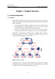
Installation Manual H3C S7502 Ethernet Switch Chapter 5 System Commissioning Chapter 5 System Commissioning 5.1 Configuration Environment Setup 5.1.1 Setting up Networking Environment A terminal (a PC in this example) is connected to the switch Console port through a Console cable. Switch Console port Serial port Console cable PC Figure 5-1 Configuration environment 5.1.
Installation Manual H3C S7502 Ethernet Switch Chapter 5 System Commissioning Taking the PC running Windows XP HyperTerminal as an example, this section introduces how to set the terminal parameters. Note: The terminal emulator on a Windows3.1 computer is Terminal and that on a Windows95/Windows98/Windows 2000/Windows NT/Windows XP/Windows ME computer is HyperTerminal. Step 1: Start the PC and run the terminal emulator.
Installation Manual H3C S7502 Ethernet Switch Chapter 5 System Commissioning Figure 5-3 Setting serial port for HyperTerminal connection 3) After selecting serial ports, click . The following interface will pop up for setting serial port parameters. Set the bits per second to 9600, data bits to 8, parity check to none, stop bits to 1, and flow control to none.
Installation Manual H3C S7502 Ethernet Switch 4) Chapter 5 System Commissioning After setting serial port parameters, click . Then the system will enter the HyperTerminal dialogue box as shown in the following figure. Figure 5-5 HyperTerminal interface In the above dialogue box, select the Properties icon to enter the properties window. Click Settings to set the attributes (see the following figure). In this interface, select terminal emulation mode VT100 and then click .
Installation Manual H3C S7502 Ethernet Switch Chapter 5 System Commissioning Figure 5-6 Setting terminal emulation mode in the property setting window 5.2 Power-on 5.2.1 Check before Power-on Before powering on an Ethernet Switch, check that: z The switch has been mounted steadily. z All the cards have been correctly installed. z All the communication cables, fibers, power cables, and grounding cables have been correctly connected.
Installation Manual H3C S7502 Ethernet Switch Chapter 5 System Commissioning Caution: Before powering on the switch, confirm where the power switch of the equipment room is located, so that you will be able to power off in case of accidence. 5.2.2 Power-on z Turn on the power supply of the switch. z Power on the switch. 5.2.3 Check after Power-on (Recommended) You are recommended to check as follows after powering on the switch to ensure the configurations thereafter.
Installation Manual H3C S7502 Ethernet Switch Chapter 5 System Commissioning SDRAM fast selftest.......................................OK! Please check LEDs.....................LEDs selftest finished! CPLD selftest.............................................OK! The switch Mac address is .....................0000.0309.0004 Press Ctrl+B to enter Boot Menu... 0 Auto-booting... Auto booting file is S7502.app There are 4 files in this packet SRPG app file <> is...OK Decompress Image...............
Installation Manual H3C S7502 Ethernet Switch Table of Contents Table of Contents Chapter 6 Hardware Maintenance................................................................................................ 6-1 6.1 Required Tools................................................................................................................... 6-1 6.2 Removing and Installing Power Module ............................................................................ 6-1 6.2.1 Installing a Power Module .....
Installation Manual H3C S7502 Ethernet Switch Chapter 6 Hardware Maintenance Chapter 6 Hardware Maintenance Caution: The power modules of the S7502 are hot-swappable. When installing or replacing an in-service power module, pay attention to operations and electrical safety. Do not touch any naked wire, terminal or any part of the product labeled with a high-voltage warning to avoid injury. 6.1 Required Tools z ESD-preventive wrist strap z Screwdriver 6.
Installation Manual H3C S7502 Ethernet Switch Chapter 6 Hardware Maintenance Caution: z Note the direction of the power module. When you insert the power module, let the side with the label face upward. z To avoid breaking or cranking the power terminals, slide the module gently into the slot. If the module is not properly aligned, slide it out and insert it again. Step 3: Fasten the captive screws to fix the power module on the chassis. See ② in Figure 6-1.
Installation Manual H3C S7502 Ethernet Switch Chapter 6 Hardware Maintenance 3 3 1 2 2 Figure 6-2 Install a card 6.3.1 Installing a Card 1) Wear an ESD-preventive wrist strap and loose the captive screws on the blank panel on the slot, where the card should be inserted. 2) Hold the ejector levers on the card with both hands and pull them outward. Slide the card into the slot along the guides. Push the card until the positioning pin on its handle touches the hole in the chassis. See ① in Figure 6-2.
Installation Manual H3C S7502 Ethernet Switch Chapter 6 Hardware Maintenance 6.4 Removing and Installing Fan Tray Caution: Do not touch any naked wire, terminal or any part of the product labeled with a high-voltage warning to avoid bodily injury. 2 1 Figure 6-3 Install a fan tray 1) Wear an ESD-preventive wrist strap and loose the captive screws on the fan tray.
Installation Manual H3C S7502 Ethernet Switch Chapter 6 Hardware Maintenance Caution: Install a new fan tray soon after removing the old one to ensure that the switch can work normally. 6.5 Installing the Mounting Brackets and Cable Management Bracket Two mounting brackets and a cable management bracket are shipped with the S7502. Take the following steps to install the mounting brackets and cable management bracket: 1) Face the LPU slots of the switch.
Installation Manual H3C S7502 Ethernet Switch Table of Contents Table of Contents Chapter 7 Software Maintenance................................................................................................. 7-1 7.1 Introduction to Loading Approaches .................................................................................. 7-1 7.1.1 Loading Software Remotely and Locally through Command Lines ........................ 7-1 7.1.2 Loading Software Locally through Boot Menu ..........................
Installation Manual H3C S7502 Ethernet Switch Chapter 7 Software Maintenance Chapter 7 Software Maintenance You can use either the command lines or BOOT menu to load software onto the S7502. 7.1 Introduction to Loading Approaches 7.1.1 Loading Software Remotely and Locally through Command Lines You can load the software: z By FTP z By TFTP 7.1.
Installation Manual H3C S7502 Ethernet Switch Chapter 7 Software Maintenance Note: The steps that you should take to load Boot ROM program are the same as those you take to load host software, except that in a Boot ROM program loading process you need to press and after accessing the Boot ROM menu and will view a different prompt message. Boot ROM loading steps are described below as an example. 7.2.
Installation Manual H3C S7502 Ethernet Switch Chapter 7 Software Maintenance Note: To access Boot Menu, press within five seconds after the screen prompts “Press Ctrl+B to enter Boot Menu...” Otherwise, the system will start executing the program decompression and at this time if you want to access Boot Menu, you will have to reboot the switch.
Installation Manual H3C S7502 Ethernet Switch Chapter 7 Software Maintenance sends an acknowledgement character; if the check fails, it sends a reject character. Upon the receipt of the acknowledgement, the sending program continues to send the next packet; upon the receipt of the reject, it retransmits the packet. II. Loading Boot ROM Follow these steps to download the Boot ROM program: Step 1: Press and in the Boot Menu to display the Boot ROM update menu: SRPU bootrom update menu: 1.
Installation Manual H3C S7502 Ethernet Switch Chapter 7 Software Maintenance Step 5: Select [File/Properties] in the HyperTerminal window, click in the popup dialog box, and select the baud rate of 115200bps in the console port configuration dialog box.
Installation Manual H3C S7502 Ethernet Switch Chapter 7 Software Maintenance Figure 7-2 Console port configuration dialog box Step 6: Click the Disconnect icon to disconnect the HyperTerminal from the switch and then click the Connect icon to re-establish the connection using the new baud rate setting. Note: After changing the baud rate setting, you must disconnect and reconnect the terminal emulator to validate the new configuration. Step 7: Press to start program downloading.
Installation Manual H3C S7502 Ethernet Switch Chapter 7 Software Maintenance Figure 7-3 File Sending dialog box Step 9: Click . The system displays the following interface. Figure 7-4 Sending file interface After completing the downloading, the system displays the following information: Downloading ...CCCCCCCCCCCCCCCCCCCCCCCCCCCCCCCCCCCCCCCCCCCCCCCCCCC.
Installation Manual H3C S7502 Ethernet Switch Chapter 7 Software Maintenance Checking flash......done! SRPU bootrom update menu: 1. Set TFTP protocol parameter 2. Set FTP protocol parameter 3. Set XMODEM protocol parameter 0. Return to boot menu Enter your choice(0-3):3 Step 11: Type <3> to return to the Boot Menu. Then type <0> to reboot the system and the system displays the following information: Rebooting...
Installation Manual H3C S7502 Ethernet Switch Chapter 7 Software Maintenance The following describes how to load the software when the S7502 switch functions as a TFTP client. II. Loading Boot ROM Step 1: Connect the switch to the PC,, which saves the file to be downloaded, through the Ethernet port for management and upgrade. The IP address of the PC is required. Connect the switch to another PC through the Console port. The two PCs can be the same one.
Installation Manual H3C S7502 Ethernet Switch Chapter 7 Software Maintenance Step 6: Type to start file downloading or to return to the program downloading menu. Suppose you type . The system starts Boot ROM program downloading and upon its completion automatically starts Boot ROM loading. The system displays the following information upon the completion of the entire process: Prepare for loading...OK! Loading....................................................
Installation Manual H3C S7502 Ethernet Switch Chapter 7 Software Maintenance Caution: z FTP Server program is not shipped with the S7502 switch. z When loading Boot ROM and host software, you must use a crossover cable to connect to the Ethernet port for upgrade. Step 3: Run the terminal emulation program on the PC connected to the console port. Start the switch, enter the Boot Menu, and then enter the download protocol menu.
Installation Manual H3C S7502 Ethernet Switch Chapter 7 Software Maintenance III. Loading host software Follow these steps to download the host software: Step 1: Select <1> from Boot Menu. The system displays the following information: 1. Set TFTP protocol parameter 2. Set FTP protocol parameter 3. Set XMODEM protocol parameter 0. Return to boot menu Enter your choice(0-3):3 The subsequent steps are the same as those for loading Boot ROM, except for the messages displayed. 7.
Installation Manual H3C S7502 Ethernet Switch Chapter 7 Software Maintenance Follow these steps after logging in to the switch. Step 1: Download the software to the switch through FTP. ftp 10.10.110.1 Trying ... Press CTRL+K to abort Connected. 220 WFTPD 2.0 service (by Texas Imperial Software) ready for new user User(none):lyt 331 Give me your password, please Password: 230 Logged in successfully [ftp] get Switchbtm.app Switchbtm.
Installation Manual H3C S7502 Ethernet Switch Chapter 7 Software Maintenance that is no longer in use.) Then you can upload the host program to the switch through FTP. Note that the switch cannot be powered off during loading process. 7.3.2 Loading by TFTP Remote loading by TFTP is similar to loading by FTP, except that the protocol used for downloading is TFTP. In this case, the switch can only be used as a TFTP client to download the software to its Flash from the TFTP server.
Installation Manual H3C S7502 Ethernet Switch Chapter 7 Software Maintenance The current application file is :SWITCH000.app The backup application file is : SWITCH100.app Free Space : 471040 bytes The system shows all the files in the Flash, wherein the one with an asterisk (*) is the primary file and the one with a hyphen (-) is the backup file. Step 3: Re-configure the primary and backup files. z Set the primary file.
Installation Manual H3C S7502 Ethernet Switch Chapter 7 Software Maintenance Note: z If you specify only the primary file, and set no backup file, the system boots with the primary file. If the primary file has any error, the system randomly chooses an application file for booting. z If you specify only the backup file, and set no primary file, the system boots with the backup file.
Installation Manual H3C S7502 Ethernet Switch Chapter 7 Software Maintenance Step 4: Upgrade the Boot ROM of the SRPU and LPU using the combined host software file. boot bootrom S7502btm.btm slot 0 1 Upgrade board 0 BOOTROM succeeded! Board 1 upgrading BOOTROM, please wait... Load finished! Start Upgrading... Frame 0 IO Board 1 upgrade BOOTROM succeeded! By now, you have completed the Boot ROM upgrade. 7.6 Handling Loading Failure If loading fails, the system runs the original version.
Installation Manual H3C S7502 Ethernet Switch Table of Contents Table of Contents Chapter 8 Troubleshooting .......................................................................................................... 8-1 8.1 Troubleshooting Configuration System ............................................................................. 8-1 8.1.1 No Display on the Terminal..................................................................................... 8-1 8.1.2 Illegible Characters on the Terminal ...
Installation Manual H3C S7502 Ethernet Switch Chapter 8 Troubleshooting Chapter 8 Troubleshooting Although the S7502 has passed the comprehensive and strict test before delivery, faults may occur due to improper installation. This chapter describes how to handle faults caused by improper installation. On the SRPU of the S7502, you can find the status LEDs of LPU, power module, and fan. You can check these status LEDs to locate the faults. 8.
Installation Manual H3C S7502 Ethernet Switch Chapter 8 Troubleshooting according to the correct one listed Section 8.1.1 “No Display on the Terminal” on page 8-1. 8.2 Troubleshooting Power Supply Table 8-1 Description of power LED LED OK (Green) FAIL (Red) Status Description ON The power supply works normally. OFF The power supply is faulty or is not installed. ON The power supply is faulty. OFF The power supply works normal or is not installed.
Installation Manual H3C S7502 Ethernet Switch Chapter 8 Troubleshooting Table 8-3 Description of card LEDs LED RUN (Green) ALM (Red) z Status Description ON/OFF The card is faulty or is not installed yet. Blinking The card works normally. OFF The card is faulty or is not installed yet. ON The card works abnormally. If the ALM LED of a card stays on, something is wrong with the card. When you reset the card, the ALM LED will turn on. After normal booting, the LED will be off.
Installation Manual H3C S7502 Ethernet Switch Table of Contents Table of Contents Appendix A Installation of Lightning Arrester for AC Power (Lightning Protection Grounding Strip) ...............................................................................................................................................
Installation Manual H3C S7502 Ethernet Switch Appendix A Installation of Lightning Arrester for AC Power (Lightning Protection Grounding Strip) Appendix A Installation of Lightning Arrester for AC Power (Lightning Protection Grounding Strip) Caution: No lightning arrester is shipped with the switch. You should purchase a lightning arrester if needed.
Installation Manual H3C S7502 Ethernet Switch Appendix A Installation of Lightning Arrester for AC Power (Lightning Protection Grounding Strip) Caution: z Make sure that the arrester is well grounded before using the lightning arrester for power. z After inserting AC power cable connector of switch into the socket of lightning arrester, if the green LED is on and the red LED does not alarm, the lightning arrester of power is running and the function of lightning protection has taken effect.
Installation Manual H3C S7502 Ethernet Switch Table of Contents Table of Contents Appendix B AC Power Cables Used in Different Countries......................................................B-1 B.1 10A AC Power Cables Used in Different Countries ..........................................................B-1 B.2 16 AC Power Cables Used in Different Countries.............................................................
Installation Manual H3C S7502 Ethernet Switch Appendix B AC Power Cables Used in Different Countries Appendix B AC Power Cables Used in Different Countries B.
Installation Manual H3C S7502 Ethernet Switch Appendix B AC Power Cables Used in Different Countries Countries where the type of power cable Other countries using Countries seldom Connect conforms to local this type of power using this type of Code (Length) or type safety regulations cable power cable and can be used legally 3 F type 04041056 (3m) Holland, Denmark, Sweden, Finland, Norway, Germany, France, Austria, Belgium, and Italy Connector outline Indonesia, Turkey, Russia, and CIS Power cable
Installation Manual H3C S7502 Ethernet Switch Connecto r type 5 B type Code (Length) 04040887 (3m) Appendix B AC Power Cables Used in Different Countries Countries where the type of power cable Other countries using Countries seldom conforms to local this type of power using this type of safety regulations cable power cable and can be used legally Japan Connector outline Power cable outline Connector outline Countries where the type of power cable Other countries using Countries seldom Connect co
Installation Manual H3C S7502 Ethernet Switch Appendix B AC Power Cables Used in Different Countries Countries where the type of power cable Other countries using Countries seldom Connect conforms to local this type of power using this type of Code (Length) or type safety regulations cable power cable and can be used legally 8 J type 04041119 (3m) Connector outline Switzerland Power cable outline Connector outline Countries where the type of power cable Other countries using Countries seldom Connect
Installation Manual H3C S7502 Ethernet Switch Appendix B AC Power Cables Used in Different Countries B.
Installation Manual H3C S7502 Ethernet Switch Connec tor type F type 5 Code (Length) 0404A061 (3m) Connector outline Connec tor type G type 7 Code (Length) 0404A060 (3m) Connector outline Appendix B AC Power Cables Used in Different Countries Countries where the type of power cable conforms to local safety regulations and can be used legally Holland, Denmark, Sweden, Finland, Norway, Germany, France, Austria, Belgium, and Italy Other countries using this type of power cable Indonesia, Turkey,
Installation Manual H3C S7502 Ethernet Switch Connec tor type B type 9 0404A062 (3m) Connector outline Connec tor type 1 3 Code (Length) I type Code (Length) 0404A01A (3m) Connector outline Appendix B AC Power Cables Used in Different Countries Countries where the type of power cable conforms to local safety regulations and can be used legally Other countries using this type of power cable Countries seldom using this type of power cable Japan Power cable outline Countries where the type of