
H3C S7502 Ethernet Switch Installation Manual
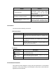

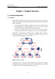
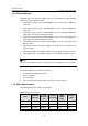
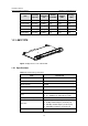
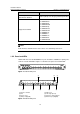
Table Of Contents
- 00-1Cover.pdf
- 01-Chapter 1 Product Overview.pdf
- 02-Chapter 2 Line Processing Units.pdf
- 03-Chapter 3 nstallation Preparations.pdf
- 04-Chapter 4 Hardware Installation.pdf
- Chapter 4 Hardware Installation
- 05-Chapter 5 System Commissioning.pdf
- 06-Chapter 6 Hardware Maintenance.pdf
- 07-Chapter 7 Software Maintenance.pdf
- Chapter 7 Software Maintenance
- 7.1 Introduction to Loading Approaches
- 7.2 Loading Software Locally through Boot Menu
- 7.3 Loading Software Remotely or Locally through Command Lines
- 7.4 Booting the Switch with Dual Images
- 7.5 Loading a Host Software Containing the Boot ROM File
- 7.6 Handling Loading Failure
- 7.7 Handling Password Loss
- Chapter 7 Software Maintenance
- 08-Chapter 8 Troubleshooting.pdf
- 09-Appendix A Lightning Protection.pdf
- 10-Appendix B AC Power Cables Used in Different Countries.pdf
Installation Manual
H3C S7502 Ethernet Switch Chapter 1 Product Overview
1-4
Item LS81P12TE
Ethernet port cable and max
transmission distance
100 m (328 ft) over category-5 twisted pair cable
Supported standard
z IEEE 802.3
z IEEE 802.3u
z IEEE 802.3z
z IEEE 802.3ab
z IEEE 802.1p
z IEEE 802.1Q
z IEEE 802.1D
z IEEE802.1X
z IEEE802.1s
z IEEE802.1w
z IEEE 802.3x
z IEEE 802.3ad
Note:
In this manual, card dimensions refer to those of a card with ejector levers.
1.2.2 Panel and LEDs
LS81P12TE has four 10/100/1000Base-T ports and twelve 1000Base-X (SFP) ports;
each has a status LED with it.
Figure 1-3 illustrates the panel of an LS81P12TE.
Figure 1-3 LS81P12TE panel
(1)
(2)
(5)(6)
(3)
(4)
(7)(8)
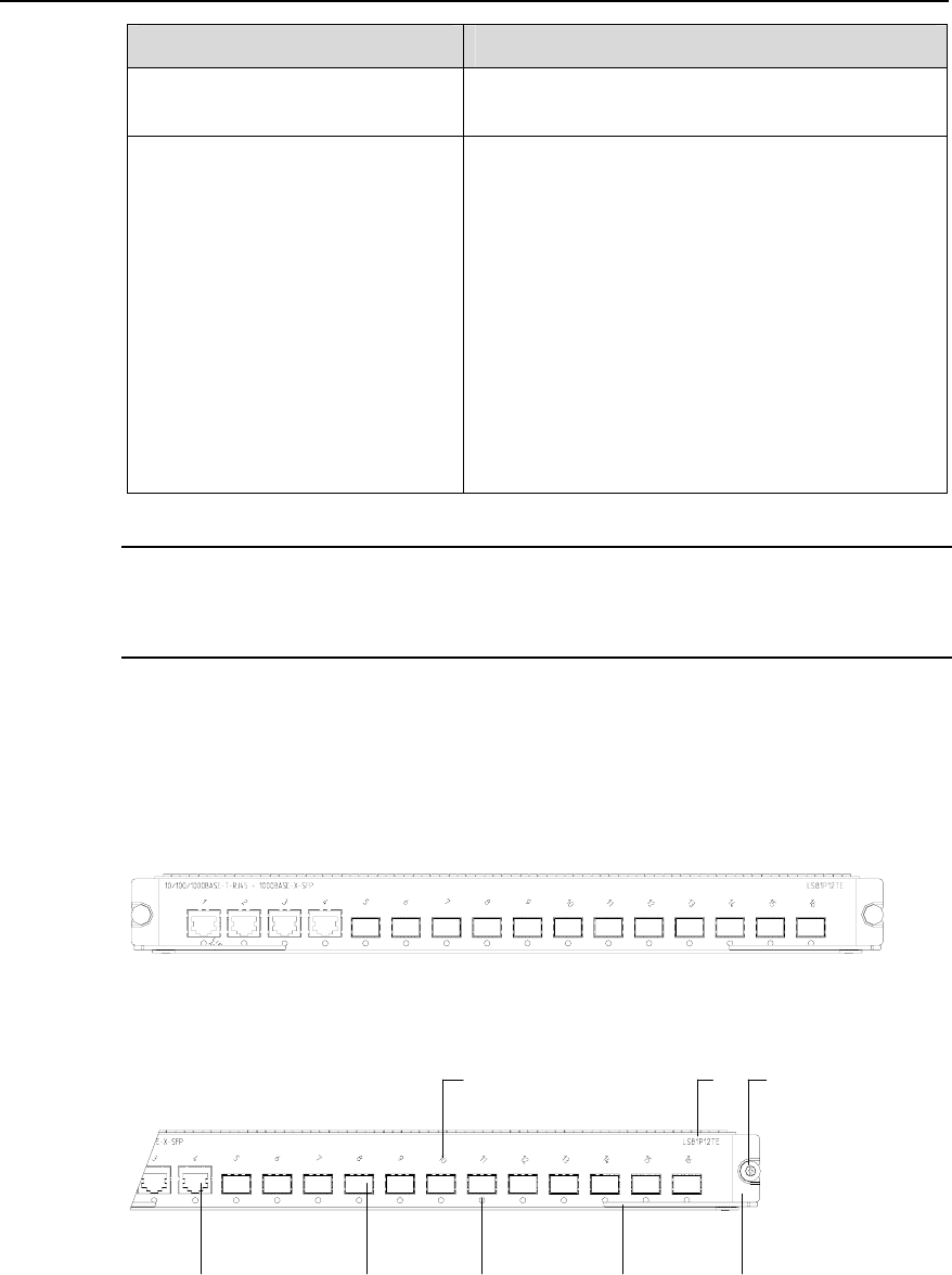
(1) Interface number (2) Silkscreen
(3) Nut (4) LPU edge (Green)
(5) Ejector lever (6) Interface status indicator
(7) SPF port (Gigabit) (8) Ethernet port (Gigabit)
Figure 1-4 LS81P12TE panel