
H3C S7502 Ethernet Switch Installation Manual

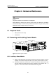
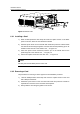
Table Of Contents
- 00-1Cover.pdf
- 01-Chapter 1 Product Overview.pdf
- 02-Chapter 2 Line Processing Units.pdf
- 03-Chapter 3 nstallation Preparations.pdf
- 04-Chapter 4 Hardware Installation.pdf
- Chapter 4 Hardware Installation
- 05-Chapter 5 System Commissioning.pdf
- 06-Chapter 6 Hardware Maintenance.pdf
- 07-Chapter 7 Software Maintenance.pdf
- Chapter 7 Software Maintenance
- 7.1 Introduction to Loading Approaches
- 7.2 Loading Software Locally through Boot Menu
- 7.3 Loading Software Remotely or Locally through Command Lines
- 7.4 Booting the Switch with Dual Images
- 7.5 Loading a Host Software Containing the Boot ROM File
- 7.6 Handling Loading Failure
- 7.7 Handling Password Loss
- Chapter 7 Software Maintenance
- 08-Chapter 8 Troubleshooting.pdf
- 09-Appendix A Lightning Protection.pdf
- 10-Appendix B AC Power Cables Used in Different Countries.pdf
Installation Manual
H3C S7502 Ethernet Switch Chapter 6 Hardware Maintenance
6-1
Chapter 6 Hardware Maintenance
Caution:
The power modules of the S7502 are hot-swappable.
When installing or replacing an in-service power module, pay attention to operations
and electrical safety. Do not touch any naked wire, terminal or any part of the product
labeled with a high-voltage warning to avoid injury.
6.1 Required Tools
z ESD-preventive wrist strap
z Screwdriver
6.2 Removing and Installing Power Module
2
2
1
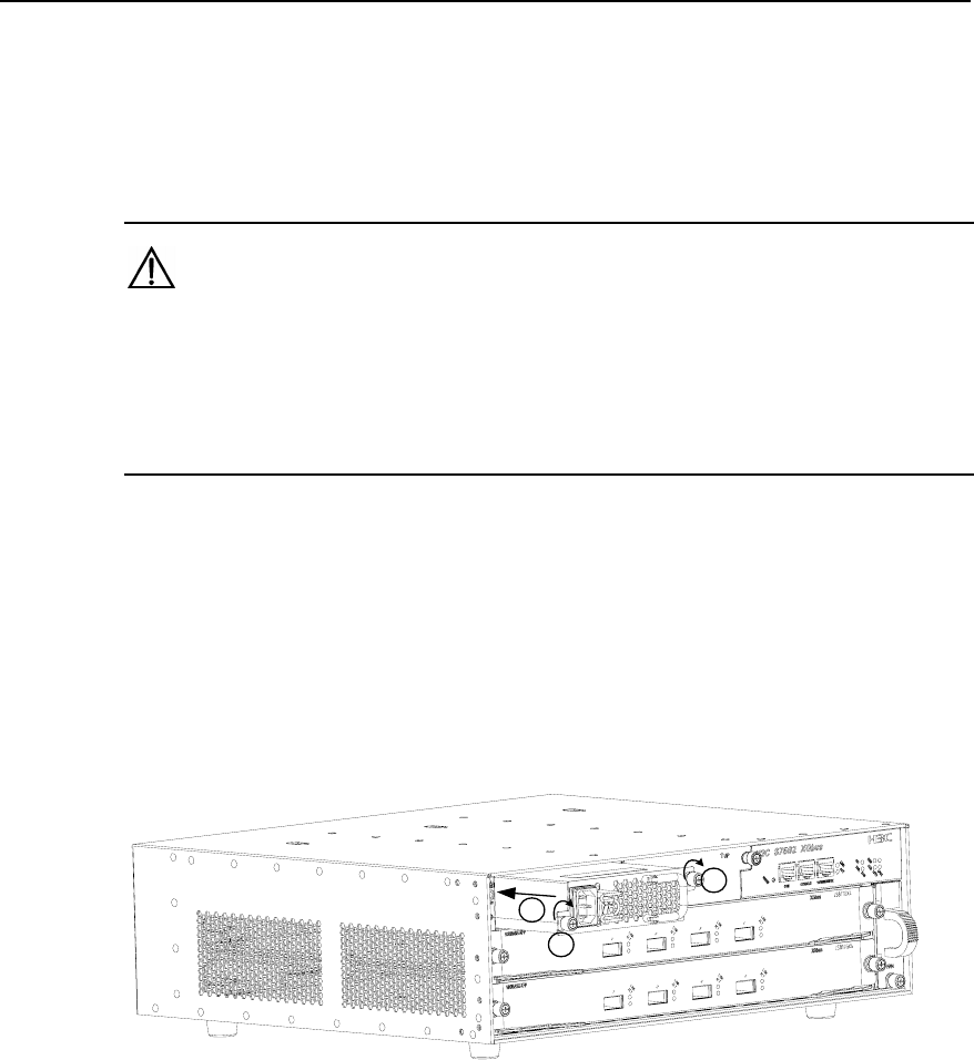
Figure 6-1 Install a power module
6.2.1 Installing a Power Module
1) Wear an ESD-preventive wrist strap and take the new power module out of the
package. Check that the input mode (DC or AC) of the power module is correct.
2) Grasp the handle of the module with one hand and hold the module bottom with
the other. Slide the module slowly along the guide rail into the chassis. See ① in
Figure 6-1. Ensure the module is well contacted with the guides.