
H3C S7502 Ethernet Switch Installation Manual
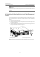
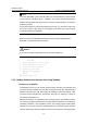
Table Of Contents
- 00-1Cover.pdf
- 01-Chapter 1 Product Overview.pdf
- 02-Chapter 2 Line Processing Units.pdf
- 03-Chapter 3 nstallation Preparations.pdf
- 04-Chapter 4 Hardware Installation.pdf
- Chapter 4 Hardware Installation
- 05-Chapter 5 System Commissioning.pdf
- 06-Chapter 6 Hardware Maintenance.pdf
- 07-Chapter 7 Software Maintenance.pdf
- Chapter 7 Software Maintenance
- 7.1 Introduction to Loading Approaches
- 7.2 Loading Software Locally through Boot Menu
- 7.3 Loading Software Remotely or Locally through Command Lines
- 7.4 Booting the Switch with Dual Images
- 7.5 Loading a Host Software Containing the Boot ROM File
- 7.6 Handling Loading Failure
- 7.7 Handling Password Loss
- Chapter 7 Software Maintenance
- 08-Chapter 8 Troubleshooting.pdf
- 09-Appendix A Lightning Protection.pdf
- 10-Appendix B AC Power Cables Used in Different Countries.pdf
Installation Manual
H3C S7502 Ethernet Switch Chapter 6 Hardware Maintenance
6-5
Caution:
Install a new fan tray soon after removing the old one to ensure that the switch can work
normally.
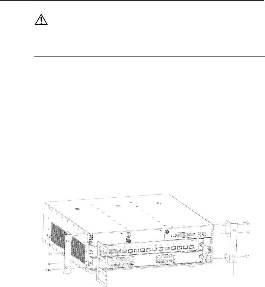
6.5 Installing the Mounting Brackets and Cable Management
Bracket
Two mounting brackets and a cable management bracket are shipped with the S7502.
Take the following steps to install the mounting brackets and cable management
bracket:
1) Face the LPU slots of the switch.
2) Attach the shipped left and right mounting brackets onto the left and right sides of
the chassis, respectively.
3) Install the shipped cable management bracket onto the left side (opposite to the
fan tray) of the chassis, as shown in
Figure 6-4.
(1)(2)
(1)
1) Mounting brackets 2) Cable management bracket
Figure 6-4 Install mounting brackets and cable management bracket on the S7502