
H3C S7502 Ethernet Switch Installation Manual
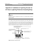
Table Of Contents
- 00-1Cover.pdf
- 01-Chapter 1 Product Overview.pdf
- 02-Chapter 2 Line Processing Units.pdf
- 03-Chapter 3 nstallation Preparations.pdf
- 04-Chapter 4 Hardware Installation.pdf
- Chapter 4 Hardware Installation
- 05-Chapter 5 System Commissioning.pdf
- 06-Chapter 6 Hardware Maintenance.pdf
- 07-Chapter 7 Software Maintenance.pdf
- Chapter 7 Software Maintenance
- 7.1 Introduction to Loading Approaches
- 7.2 Loading Software Locally through Boot Menu
- 7.3 Loading Software Remotely or Locally through Command Lines
- 7.4 Booting the Switch with Dual Images
- 7.5 Loading a Host Software Containing the Boot ROM File
- 7.6 Handling Loading Failure
- 7.7 Handling Password Loss
- Chapter 7 Software Maintenance
- 08-Chapter 8 Troubleshooting.pdf
- 09-Appendix A Lightning Protection.pdf
- 10-Appendix B AC Power Cables Used in Different Countries.pdf
Installation Manual
H3C S7502 Ethernet Switch
Appendix A Installation of Lightning Arrester for AC Power
(Lightning Protection Grounding Strip)
A-1
Appendix A Installation of Lightning Arrester for
AC Power (Lightning Protection Grounding Strip)
Caution:
No lightning arrester is shipped with the switch. You should purchase a lightning
arrester if needed.
If an outdoor AC power cable should be directly led to the switch, please serially
connect the lightning arrester for AC power (lightning protection grounding strip) before
you plug AC power cable into the switch, thus to prevent the possible damage to the
switch due to lightning strike. You can use cable clips and screws to fasten the lightning
arrester for AC power on the cabinet, workbench or the wall of equipment room.
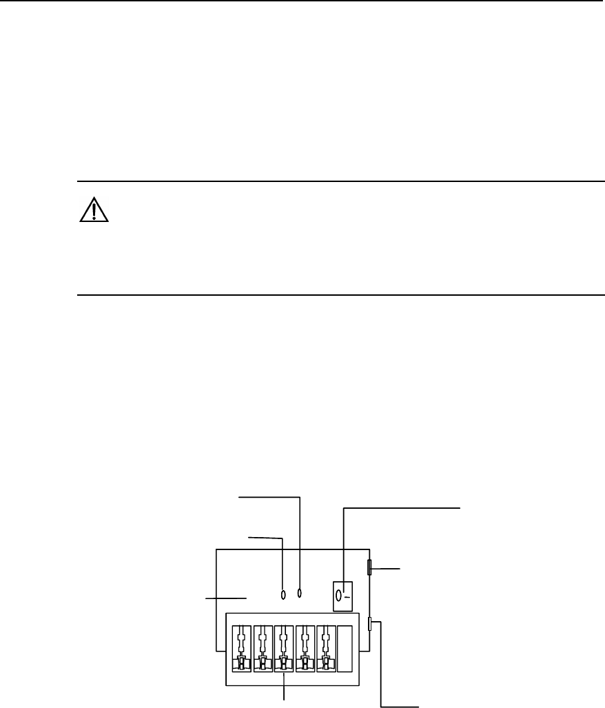
Mainboard
Grounding and polarity indicator (red) :
On means that the lines are wrongly connected
Please check the power supply circuit.
Power switch
Normal operation indicator (green):
On means that the arrester works normally.
Otherwise, the protection circuit has
been damaged
.
Multipurpose power socket, connected to the device
protected by the arrester
Power socket (complied with IEC standard),
connected to the power supply of
the equipment room through power cord
Overload auto protector,
which can be manually reset.
Mainboard
(either the grounding cable is not well connected, or the live and zero lines are wrongly connected)
.
Figure A-1 Diagram of lightning arrester