
H3C S7502 Ethernet Switch Installation Manual
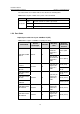
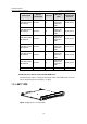
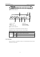
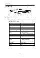
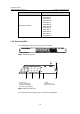
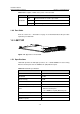
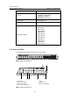
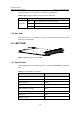
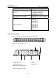
Table Of Contents
- 00-1Cover.pdf
- 01-Chapter 1 Product Overview.pdf
- 02-Chapter 2 Line Processing Units.pdf
- 03-Chapter 3 nstallation Preparations.pdf
- 04-Chapter 4 Hardware Installation.pdf
- Chapter 4 Hardware Installation
- 05-Chapter 5 System Commissioning.pdf
- 06-Chapter 6 Hardware Maintenance.pdf
- 07-Chapter 7 Software Maintenance.pdf
- Chapter 7 Software Maintenance
- 7.1 Introduction to Loading Approaches
- 7.2 Loading Software Locally through Boot Menu
- 7.3 Loading Software Remotely or Locally through Command Lines
- 7.4 Booting the Switch with Dual Images
- 7.5 Loading a Host Software Containing the Boot ROM File
- 7.6 Handling Loading Failure
- 7.7 Handling Password Loss
- Chapter 7 Software Maintenance
- 08-Chapter 8 Troubleshooting.pdf
- 09-Appendix A Lightning Protection.pdf
- 10-Appendix B AC Power Cables Used in Different Countries.pdf
Installation Manual
H3C S7502 Ethernet Switch Chapter 1 Product Overview
1-8
Figure 1-6 LS81T12PE panel
(1) (2)
(5)(6)(7)
(3)
(4)
(8)
(1) Interface number (2) Silkscreen
(3) Nut (4) LPU edge (Green)
(5) Ejector lever (6) SPF port (Gigabit)
(7) Interface status LED (8) Ethernet port (Gigabit)
Figure 1-7 LS81T12PE panel
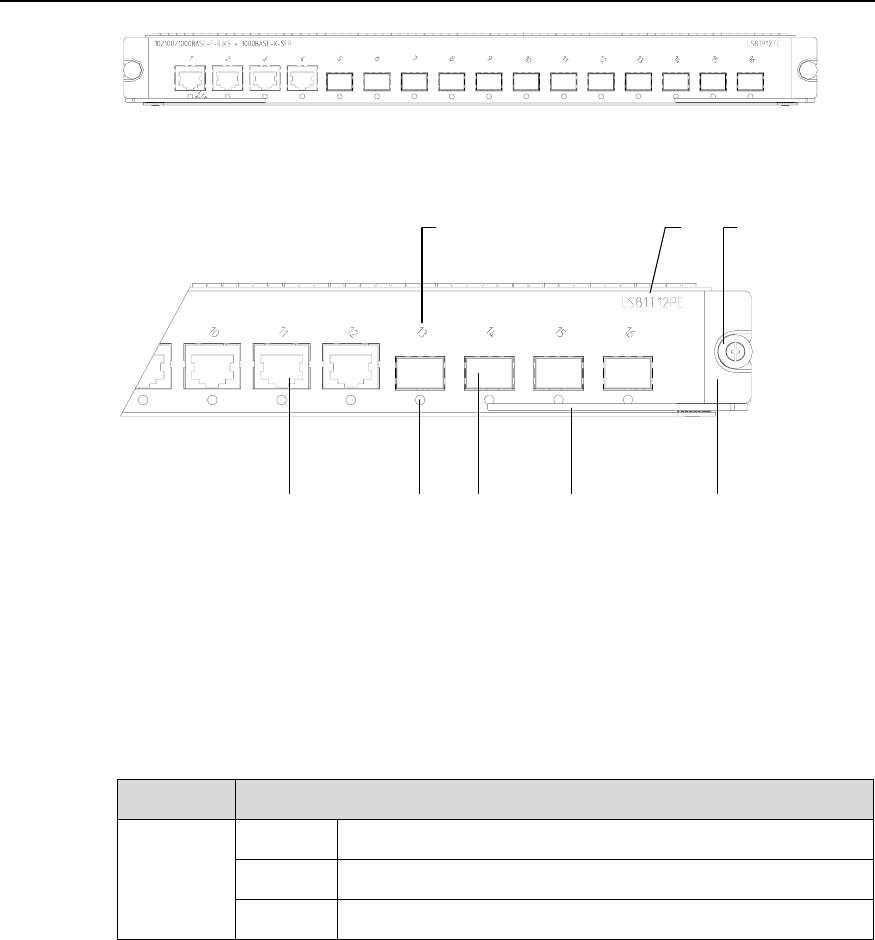
The status LEDs on an LS81T12PE are described in
Table 1-6.
Table 1-6 Description of LEDs on the panel of an LS81T12PE
LED Status
OFF The link is down or no link is presented.
ON The link is active.
LINK/ACT
Blinking Data is being transmitted or received on the port.
1.3.3 Port Cable
Refer to section 1.2.3 "Port Cable” on page 1-5 for information about the port cable
required by an LS81T12PE.