
H3C S7502 Ethernet Switch Installation Manual
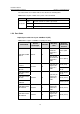
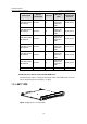
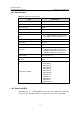
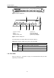
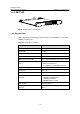
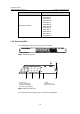
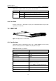
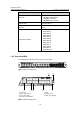
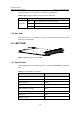
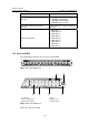
Table Of Contents
- 00-1Cover.pdf
- 01-Chapter 1 Product Overview.pdf
- 02-Chapter 2 Line Processing Units.pdf
- 03-Chapter 3 nstallation Preparations.pdf
- 04-Chapter 4 Hardware Installation.pdf
- Chapter 4 Hardware Installation
- 05-Chapter 5 System Commissioning.pdf
- 06-Chapter 6 Hardware Maintenance.pdf
- 07-Chapter 7 Software Maintenance.pdf
- Chapter 7 Software Maintenance
- 7.1 Introduction to Loading Approaches
- 7.2 Loading Software Locally through Boot Menu
- 7.3 Loading Software Remotely or Locally through Command Lines
- 7.4 Booting the Switch with Dual Images
- 7.5 Loading a Host Software Containing the Boot ROM File
- 7.6 Handling Loading Failure
- 7.7 Handling Password Loss
- Chapter 7 Software Maintenance
- 08-Chapter 8 Troubleshooting.pdf
- 09-Appendix A Lightning Protection.pdf
- 10-Appendix B AC Power Cables Used in Different Countries.pdf
Installation Manual
H3C S7502 Ethernet Switch Chapter 1 Product Overview
1-10
Item LS81T16P
Supported standard
z IEEE 802.3
z IEEE 802.3u
z IEEE 802.3z
z IEEE 802.3ab
z IEEE 802.1p
z IEEE 802.1Q
z IEEE 802.1D
z IEEE 802.1X
z IEEE 802.1s
z IEEE 802.1w
z IEEE 802.3x
z IEEE 802.3ad
1.4.2 Panel and LEDs
The following figure illustrates the panel of an LS81T16P.
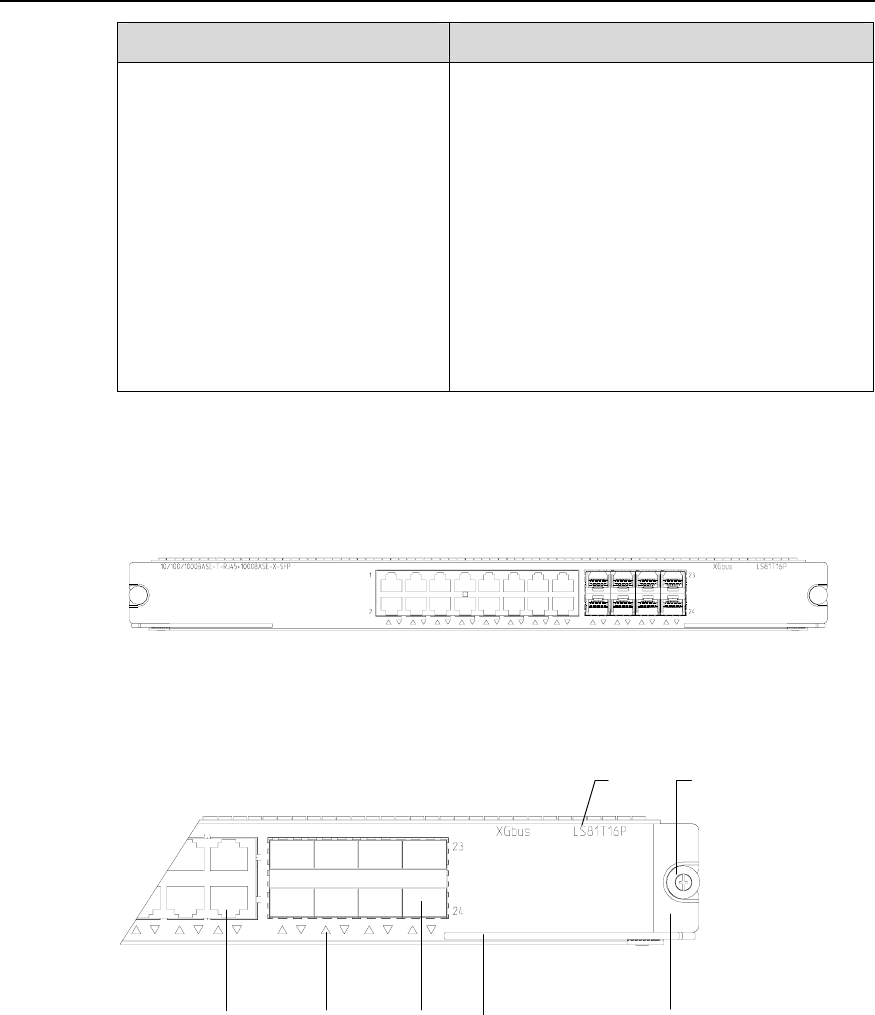
Figure 1-9 LS81T16P panel
(1) (2)
(5)(6)(7)
(3)(4)
(1) Silkscreen (2) Nut
(3) LPU edge (Green) (4) Ejector lever
(5) SPF port (Gigabit) (6) Port status LED
(7) Ethernet port (Gigabit)
Figure 1-10 LS81T16P panel
The status LEDs on an LS81T16P are described in following table