
H3C S7502 Ethernet Switch Installation Manual
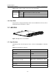
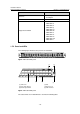
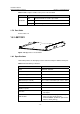
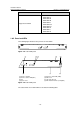
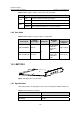
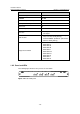
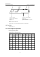
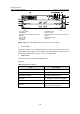
Table Of Contents
- 00-1Cover.pdf
- 01-Chapter 1 Product Overview.pdf
- 02-Chapter 2 Line Processing Units.pdf
- 03-Chapter 3 nstallation Preparations.pdf
- 04-Chapter 4 Hardware Installation.pdf
- Chapter 4 Hardware Installation
- 05-Chapter 5 System Commissioning.pdf
- 06-Chapter 6 Hardware Maintenance.pdf
- 07-Chapter 7 Software Maintenance.pdf
- Chapter 7 Software Maintenance
- 7.1 Introduction to Loading Approaches
- 7.2 Loading Software Locally through Boot Menu
- 7.3 Loading Software Remotely or Locally through Command Lines
- 7.4 Booting the Switch with Dual Images
- 7.5 Loading a Host Software Containing the Boot ROM File
- 7.6 Handling Loading Failure
- 7.7 Handling Password Loss
- Chapter 7 Software Maintenance
- 08-Chapter 8 Troubleshooting.pdf
- 09-Appendix A Lightning Protection.pdf
- 10-Appendix B AC Power Cables Used in Different Countries.pdf
Installation Manual
H3C S7502 Ethernet Switch Chapter 1 Product Overview
1-15
Table 1-12 Description of LEDs on the panel of an LS81GT48B
LED Status
OFF The link is down or no link is presented.
ON The link is active.
LINK/ACT
Blinking Data is being transmitted or received on the port.
1.6.3 Port Cable
The port cable is category-5 twisted pair cable connected with RJ45 connectors, whose
maximum transmission distance is 100 m.
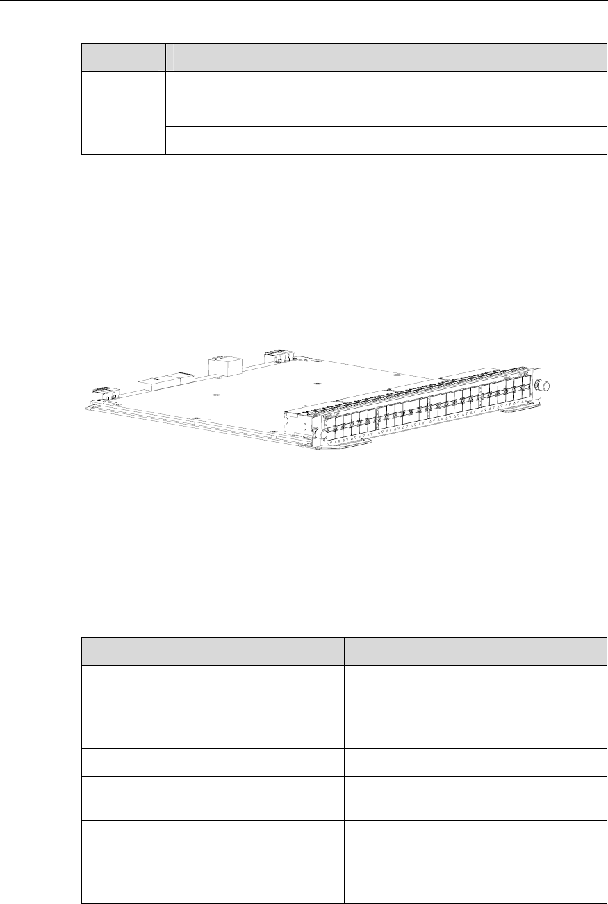
1.7 LS81GP48
Figure 1-17 Appearance of LS81GP48
1.7.1 Specifications
LS81GP48 provides the XG high-speed bus, and 48 ×10/100/1000Base-T Ethernet
ports.
Table 1-13 LS81GP48 specifications
Item LS81GP48
CPU MPC8245 300 MHz
BootROM 512 KB
Flash memory 32 MB
SDRAM 256 MB
Dimensions (H × W x D)
40.1 × 376.7 × 354.5 mm (1.6 × 14.8 ×
14 in.)
Max power consumption 75 W
Connector LC
Number of ports 48