
H3C S7502 Ethernet Switch Installation Manual
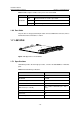
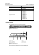
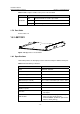
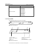
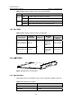
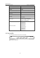
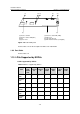
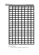
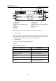
Table Of Contents
- 00-1Cover.pdf
- 01-Chapter 1 Product Overview.pdf
- 02-Chapter 2 Line Processing Units.pdf
- 03-Chapter 3 nstallation Preparations.pdf
- 04-Chapter 4 Hardware Installation.pdf
- Chapter 4 Hardware Installation
- 05-Chapter 5 System Commissioning.pdf
- 06-Chapter 6 Hardware Maintenance.pdf
- 07-Chapter 7 Software Maintenance.pdf
- Chapter 7 Software Maintenance
- 7.1 Introduction to Loading Approaches
- 7.2 Loading Software Locally through Boot Menu
- 7.3 Loading Software Remotely or Locally through Command Lines
- 7.4 Booting the Switch with Dual Images
- 7.5 Loading a Host Software Containing the Boot ROM File
- 7.6 Handling Loading Failure
- 7.7 Handling Password Loss
- Chapter 7 Software Maintenance
- 08-Chapter 8 Troubleshooting.pdf
- 09-Appendix A Lightning Protection.pdf
- 10-Appendix B AC Power Cables Used in Different Countries.pdf
Installation Manual
H3C S7502 Ethernet Switch Chapter 1 Product Overview
1-18
Item LS81TGX2
Supported standard
z IEEE 802.3
z IEEE 802.1p
z IEEE 802.1Q
z IEEE 802.1D
z IEEE 802.3x
z IEEE 802.3ad
z IEEE 802.3ae
z IEEE 802.1X
z IEEE 802.1s
z IEEE 802.1w
1.8.2 Panel and LEDs
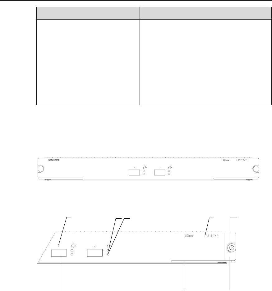
The following figure illustrates the panel of an LS81TGX2.
Figure 1-21 LS81TGX2 panel
(1)
(2)
(3) (4)
(5)
(6)(7)
(8)
(1) Interface number (2) Interface status LED (LINK)
(3) Interface status LED (ACT) (4) Silkscreen
(5) Nut (6) LPU edge (Green)
(7) Ejector lever (8) XFP module interface (10 Gigabit)
Figure 1-22 LS81TGX2 panel
The status LEDs on an LS81TGX2 are described in following table.