
H3C S7502 Ethernet Switch Installation Manual
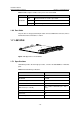
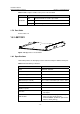
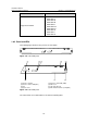
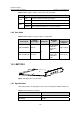
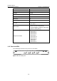
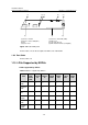
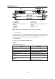
Table Of Contents
- 00-1Cover.pdf
- 01-Chapter 1 Product Overview.pdf
- 02-Chapter 2 Line Processing Units.pdf
- 03-Chapter 3 nstallation Preparations.pdf
- 04-Chapter 4 Hardware Installation.pdf
- Chapter 4 Hardware Installation
- 05-Chapter 5 System Commissioning.pdf
- 06-Chapter 6 Hardware Maintenance.pdf
- 07-Chapter 7 Software Maintenance.pdf
- Chapter 7 Software Maintenance
- 7.1 Introduction to Loading Approaches
- 7.2 Loading Software Locally through Boot Menu
- 7.3 Loading Software Remotely or Locally through Command Lines
- 7.4 Booting the Switch with Dual Images
- 7.5 Loading a Host Software Containing the Boot ROM File
- 7.6 Handling Loading Failure
- 7.7 Handling Password Loss
- Chapter 7 Software Maintenance
- 08-Chapter 8 Troubleshooting.pdf
- 09-Appendix A Lightning Protection.pdf
- 10-Appendix B AC Power Cables Used in Different Countries.pdf
Installation Manual
H3C S7502 Ethernet Switch Chapter 1 Product Overview
1-19
Table 1-16 Description of LEDs on the panel of an LS81TGX2
LED Status
OFF The link is down or no link is presented.
LINK
ON The link is active.
OFF No data is being transmitted or received on the port
ACT
Blinking Data is being transmitted or received on the port.
1.8.3 Port Cable
Table 1-17 Description on the port cables for LS81TGX2
XFP module
Central
wavelength
Connector
Matching
cable
Maximum
transmission
distance
XFP-SX-MM850 850 nm
50 µm/125 µm
multimode
optical fiber
cable
300 m (984 ft)
XFP-LX-SM1310 1310 nm
LC
9 µm/125 µm
single mode
optical fiber
cable
10 km (6 mi)
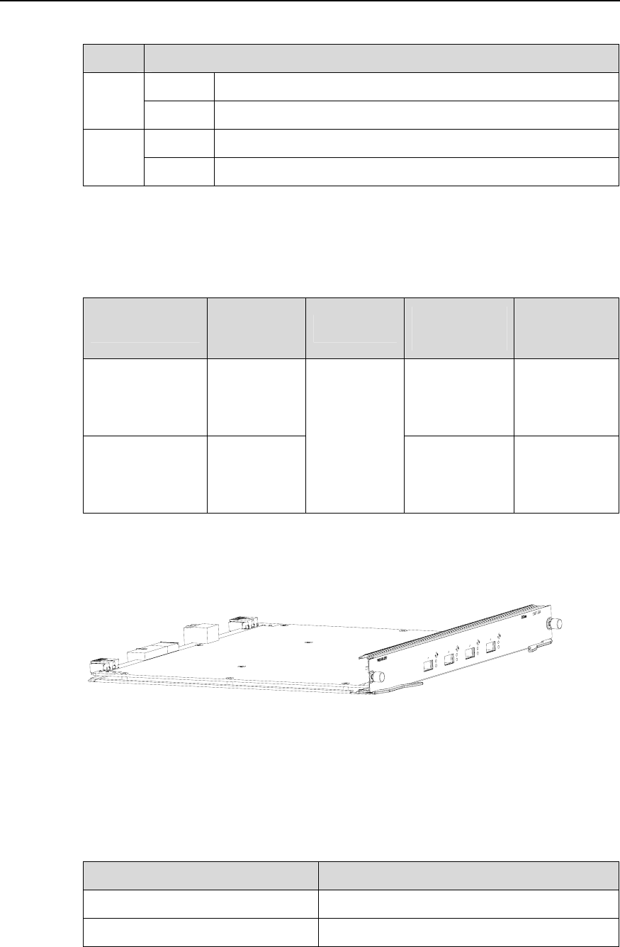
1.9 LS81TGX4
Figure 1-23 Appearance of LS81TGX4
1.9.1 Specifications
LS81TGX4 provides the XG high-speed bus and four full duplex 10GBase-XFP ports.
Table 1-18 LS81TGX4 specifications
Item LS81TGX4
CPU MPC8245 300 MHz
BootROM 512 KB