
H3C S7502 Ethernet Switch Installation Manual
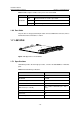
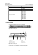
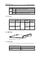
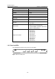
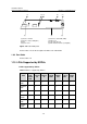
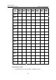
Table Of Contents
- 00-1Cover.pdf
- 01-Chapter 1 Product Overview.pdf
- 02-Chapter 2 Line Processing Units.pdf
- 03-Chapter 3 nstallation Preparations.pdf
- 04-Chapter 4 Hardware Installation.pdf
- Chapter 4 Hardware Installation
- 05-Chapter 5 System Commissioning.pdf
- 06-Chapter 6 Hardware Maintenance.pdf
- 07-Chapter 7 Software Maintenance.pdf
- Chapter 7 Software Maintenance
- 7.1 Introduction to Loading Approaches
- 7.2 Loading Software Locally through Boot Menu
- 7.3 Loading Software Remotely or Locally through Command Lines
- 7.4 Booting the Switch with Dual Images
- 7.5 Loading a Host Software Containing the Boot ROM File
- 7.6 Handling Loading Failure
- 7.7 Handling Password Loss
- Chapter 7 Software Maintenance
- 08-Chapter 8 Troubleshooting.pdf
- 09-Appendix A Lightning Protection.pdf
- 10-Appendix B AC Power Cables Used in Different Countries.pdf
Installation Manual
H3C S7502 Ethernet Switch Chapter 1 Product Overview
1-21
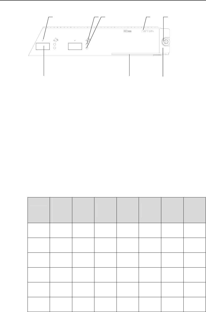
(1) (2) (3)
(4)
(7)
(5)
(6)(8)
(1) Interface number (2) Interface status LED (LINK)
(3) Interface status LED (ACT) (4) Silkscreen
(5) Nut (6) LPU edge (Green)
(7) Ejector lever (8) XFP module interface (10 Gigabit)
Figure 1-25 LS81TGX4 panel
Refer to
Table 1-16 for the description of LEDs on an LS81TGX4.
1.9.3 Port Cable
Refer to Table 1-4.
1.10 LPUs Supported by SRPUs
I. LPUs supported by SRPUs
Table 1-19 LPUs supported by SRPUs
Item
LS81T1
2PE/
LS81P1
2TE
LS81T1
6P
LS81T3
2P
LS81G
T48B
LS81G
P48
LS81T
GX2
LS81T
GX4
LS81FT
48E
√ — — — — — —
LS81FT
48F
√ — — — — —
—
LS81FP
48
√
—
—
—
—
—
—
LS81G
T8UE
√
—
—
—
—
—
—
LS82G
T20
√
—
—
—
—
—
—
LS82G
T20A
√
—
—
—
—
—
—