
H3C S7502 Ethernet Switch Installation Manual
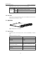
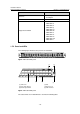
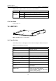
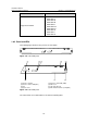
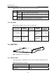
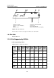
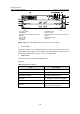
Table Of Contents
- 00-1Cover.pdf
- 01-Chapter 1 Product Overview.pdf
- 02-Chapter 2 Line Processing Units.pdf
- 03-Chapter 3 nstallation Preparations.pdf
- 04-Chapter 4 Hardware Installation.pdf
- Chapter 4 Hardware Installation
- 05-Chapter 5 System Commissioning.pdf
- 06-Chapter 6 Hardware Maintenance.pdf
- 07-Chapter 7 Software Maintenance.pdf
- Chapter 7 Software Maintenance
- 7.1 Introduction to Loading Approaches
- 7.2 Loading Software Locally through Boot Menu
- 7.3 Loading Software Remotely or Locally through Command Lines
- 7.4 Booting the Switch with Dual Images
- 7.5 Loading a Host Software Containing the Boot ROM File
- 7.6 Handling Loading Failure
- 7.7 Handling Password Loss
- Chapter 7 Software Maintenance
- 08-Chapter 8 Troubleshooting.pdf
- 09-Appendix A Lightning Protection.pdf
- 10-Appendix B AC Power Cables Used in Different Countries.pdf
Installation Manual
H3C S7502 Ethernet Switch Chapter 1 Product Overview
1-24
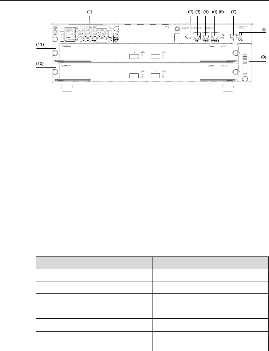
(1) Power module (2) RESET button
(3) COM port (4) Console port
(5) Ethernet port for management and
upgrade
(6) LED of Ethernet port for management and
upgrade
(7) Fan LED (8) Card status LED
(9) Fan tray (10) LPU
(11) SRPU
Figure 1-26 Panel of an S7502 switch (an AC chassis in an example)
z Power modules
The power modules, in 1+1 redundancy backup, are at the top left corner of the chassis
to provide AC power supply. There are LED, power switch and power input socket on a
power supply module (refer to
Figure 1-31 for more information).
z RESET button
You can reset the system with the RESET button.
COM port
Table 1-20 COM port attributes
Item Description
Connector RJ45
Number of connector 1
Supported standard Asynchronous EIA/TIA-232
Baudrate
≤ 115,200 bps (defaults to 9,600 bps)
Transmission distance
≤ 15 m (49.2 ft)
Function
For monitoring external PoE power
supply when connected to it