
H3C S7502 Ethernet Switch Installation Manual
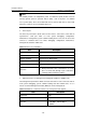
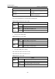
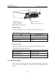
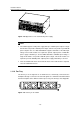
Table Of Contents
- 00-1Cover.pdf
- 01-Chapter 1 Product Overview.pdf
- 02-Chapter 2 Line Processing Units.pdf
- 03-Chapter 3 nstallation Preparations.pdf
- 04-Chapter 4 Hardware Installation.pdf
- Chapter 4 Hardware Installation
- 05-Chapter 5 System Commissioning.pdf
- 06-Chapter 6 Hardware Maintenance.pdf
- 07-Chapter 7 Software Maintenance.pdf
- Chapter 7 Software Maintenance
- 7.1 Introduction to Loading Approaches
- 7.2 Loading Software Locally through Boot Menu
- 7.3 Loading Software Remotely or Locally through Command Lines
- 7.4 Booting the Switch with Dual Images
- 7.5 Loading a Host Software Containing the Boot ROM File
- 7.6 Handling Loading Failure
- 7.7 Handling Password Loss
- Chapter 7 Software Maintenance
- 08-Chapter 8 Troubleshooting.pdf
- 09-Appendix A Lightning Protection.pdf
- 10-Appendix B AC Power Cables Used in Different Countries.pdf
Installation Manual
H3C S7502 Ethernet Switch Chapter 1 Product Overview
1-26
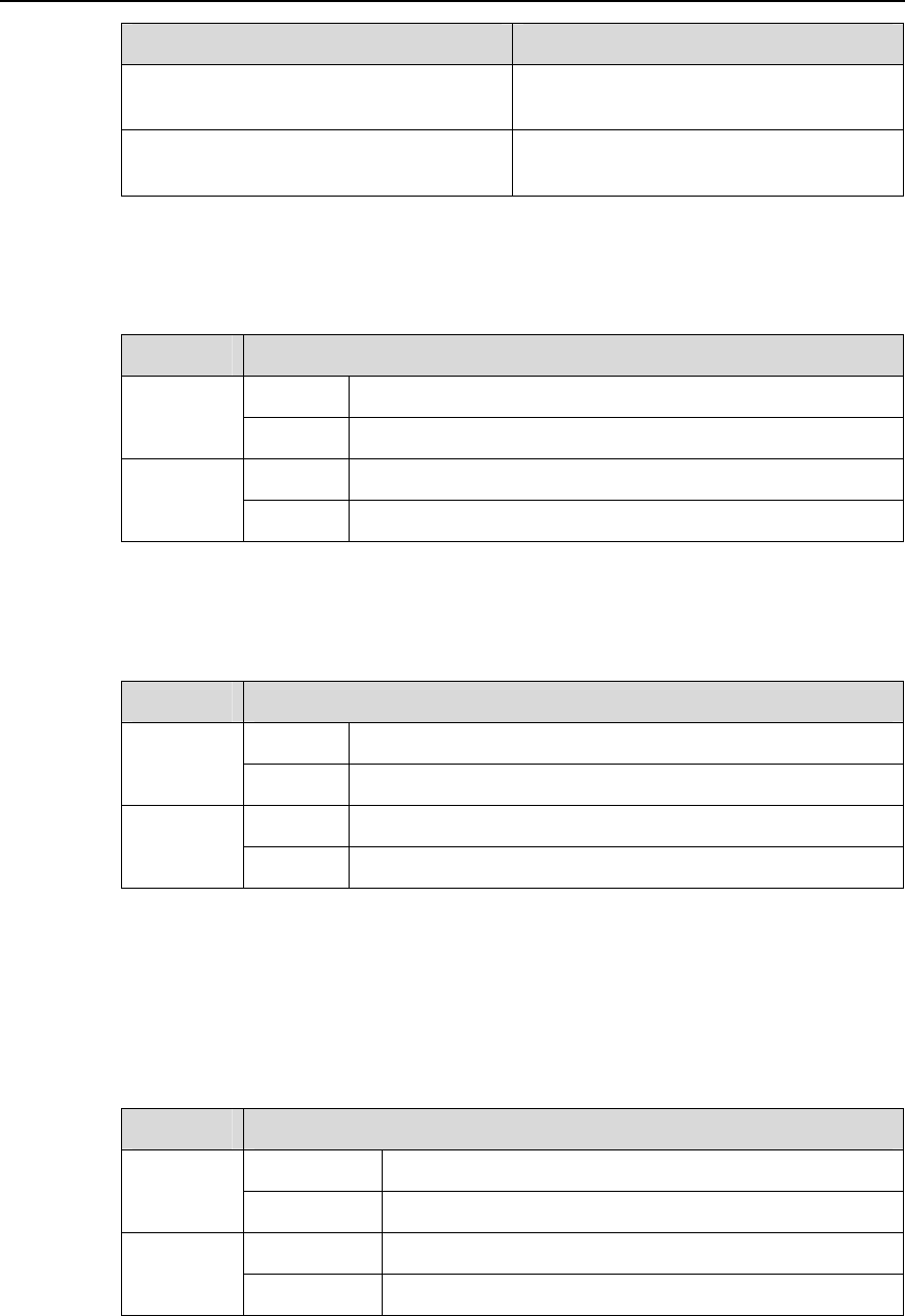
Item Description
Port cable and max transmission
distance
100 m (328 ft) over category-5 twisted
pair cable
Function
For system software upgrade and
network management
The corresponding LEDs are described in the following table.
Table 1-23 Management port status LEDs
LED Status
OFF No link is presented.
LINK
(Green)
ON A link is presented.
OFF No data traffic through the port
ACT
(Green)
Blinking Data is being transmitted or received on the port.
z Fan tray status LEDs (FAN)
Table 1-24 Fan tray status LEDs
LED Status
OFF A fan is faulty or out of position.
OK
(Green)
ON The fans run normally.
OFF The fans run normally.
FAIL
(Green)
ON A fan is faulty or out of position.
z LPU status LEDs (LPU1, LPU2)
LPU1 shows the status of the LPU in slot 0;
LPU2 shows the status of the LPU in slot 1.
Table 1-25 Card status LED
LED Status
OFF or ON The LPU is faulty or out of position.
RUN
(Green)
Blinking The LPU runs normally.
OFF The card is normal or out of position.
ALM (Red)
ON The LPU is faulty.