
H3C S7502 Ethernet Switch Installation Manual
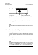
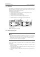
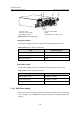
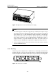
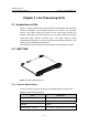
Table Of Contents
- 00-1Cover.pdf
- 01-Chapter 1 Product Overview.pdf
- 02-Chapter 2 Line Processing Units.pdf
- 03-Chapter 3 nstallation Preparations.pdf
- 04-Chapter 4 Hardware Installation.pdf
- Chapter 4 Hardware Installation
- 05-Chapter 5 System Commissioning.pdf
- 06-Chapter 6 Hardware Maintenance.pdf
- 07-Chapter 7 Software Maintenance.pdf
- Chapter 7 Software Maintenance
- 7.1 Introduction to Loading Approaches
- 7.2 Loading Software Locally through Boot Menu
- 7.3 Loading Software Remotely or Locally through Command Lines
- 7.4 Booting the Switch with Dual Images
- 7.5 Loading a Host Software Containing the Boot ROM File
- 7.6 Handling Loading Failure
- 7.7 Handling Password Loss
- Chapter 7 Software Maintenance
- 08-Chapter 8 Troubleshooting.pdf
- 09-Appendix A Lightning Protection.pdf
- 10-Appendix B AC Power Cables Used in Different Countries.pdf

Installation Manual
H3C S7502 Ethernet Switch Chapter 1 Product Overview
1-27
II. Rear view
(1)(2)(3)(4)
(1) Grounding screw (2) COM port (PSE monitoring port)
(3) RTN (+) terminal of PoE power supply
input
(4) NEG (-) terminal of PoE power supply
input
Figure 1-27 Rear view of an S7502 PoE chassis
An S7502 PoE chassis provides PoE power supply input terminals, through which the
PoE power supply outputs –48 VDC to the switch.
Note:
The backplane, SRPU, power module and fan tray all are required components for the
S7502.
1.11.2 Color Description on the Fan Tray and Cards
I. Color description on the fan tray
The slot number in the green area on the fan tray of the S7502 indicates that the slot is
for an SRPU, and the slot number in the purple area indicates that the slot is for an
LPU.
II. Color description on cards
The left and right edges of an SRPU are in green, and those of an LPU are in purple.
Note:
In an S7502 Ethernet switch, when a card with green edges is inserted into the SRPU
slot, the card acts as an SRPU; when the card is inserted into the LPU slot, the card
acts as an LPU. But a card with purple edges can be inserted only into the LPU slot.