
H3C S7502 Ethernet Switch Installation Manual
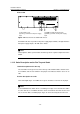
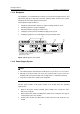
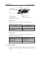
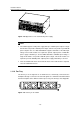
Table Of Contents
- 00-1Cover.pdf
- 01-Chapter 1 Product Overview.pdf
- 02-Chapter 2 Line Processing Units.pdf
- 03-Chapter 3 nstallation Preparations.pdf
- 04-Chapter 4 Hardware Installation.pdf
- Chapter 4 Hardware Installation
- 05-Chapter 5 System Commissioning.pdf
- 06-Chapter 6 Hardware Maintenance.pdf
- 07-Chapter 7 Software Maintenance.pdf
- Chapter 7 Software Maintenance
- 7.1 Introduction to Loading Approaches
- 7.2 Loading Software Locally through Boot Menu
- 7.3 Loading Software Remotely or Locally through Command Lines
- 7.4 Booting the Switch with Dual Images
- 7.5 Loading a Host Software Containing the Boot ROM File
- 7.6 Handling Loading Failure
- 7.7 Handling Password Loss
- Chapter 7 Software Maintenance
- 08-Chapter 8 Troubleshooting.pdf
- 09-Appendix A Lightning Protection.pdf
- 10-Appendix B AC Power Cables Used in Different Countries.pdf
Installation Manual
H3C S7502 Ethernet Switch Chapter 1 Product Overview
1-28
1.11.3 Backplane
The backplane of an S7502 Ethernet switch is located in the integrated chassis and
implements high-speed data interconnection between SRPU and LPU and system
management and control signal interconnection.
The backplane mainly functions in:
z Providing communication channels for signal exchange between cards.
z Providing support for card hot-swapping
z Auto-detecting the card type inserted at slots
z Leading in electric power for distributed supply to the system
z Leading in signal lines for monitoring the fan tray and power frame
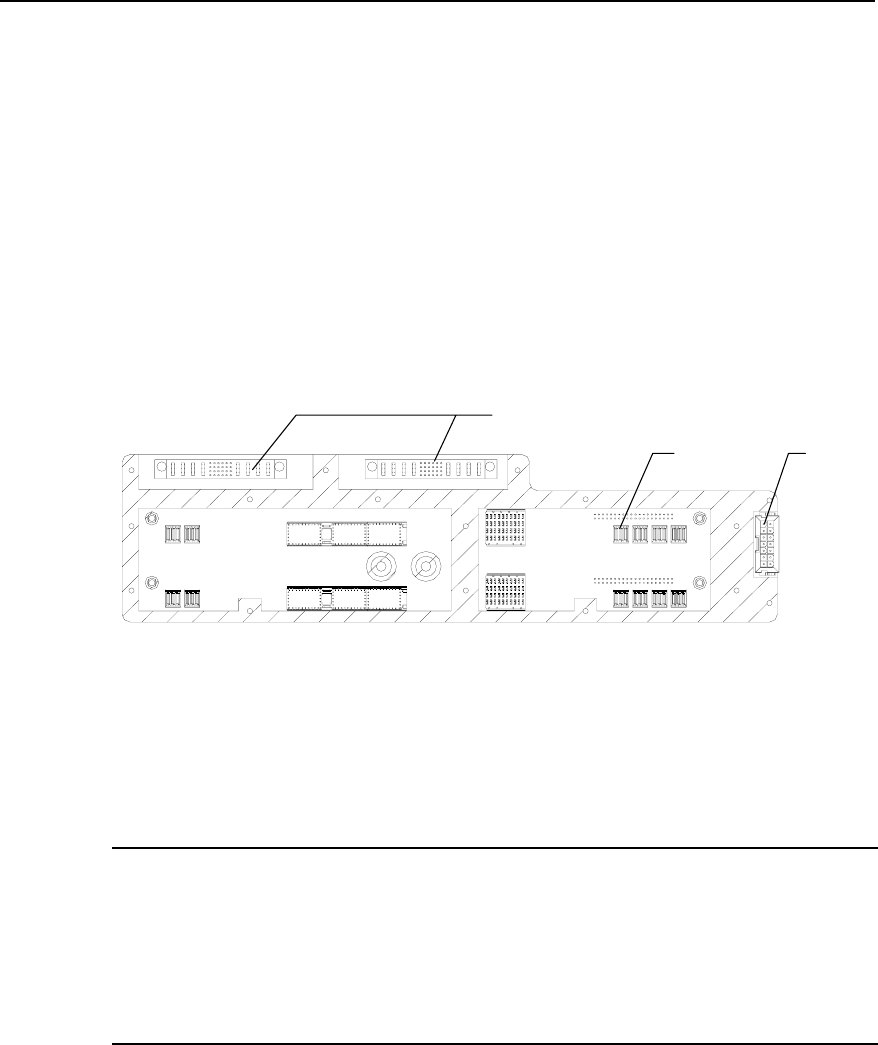
(3)(2)
(1)
(1) Power module socket (2) Card socket
(3) Fan tray socket
Figure 1-28 Backplane of the S7502
1.11.4 Power Supply System
Note:
z The S7502 supports either AC input or DC input. You can choose one as needed.
z Although one power module can ensure the normal operation of the system, the
S7502 provides two power module slots to implement 1+1 redundancy backup.
z The power module on the S7502 is hot-swappable.
The AC power module or DC power module of the S7502 meets the following
requirements:
z Both an AC power module and DC power module have exactly the same
dimensions and ports.
z Both an AC power module and DC power module have exactly the same type of
output plug-in at the same position.
z An AC power module and DC power module cannot be both inserted in one
S7502.