
H3C S7502 Ethernet Switch Installation Manual
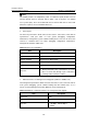
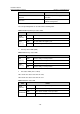
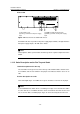
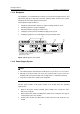
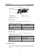
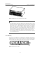
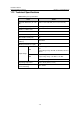
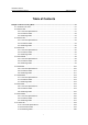
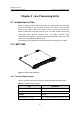
Table Of Contents
- 00-1Cover.pdf
- 01-Chapter 1 Product Overview.pdf
- 02-Chapter 2 Line Processing Units.pdf
- 03-Chapter 3 nstallation Preparations.pdf
- 04-Chapter 4 Hardware Installation.pdf
- Chapter 4 Hardware Installation
- 05-Chapter 5 System Commissioning.pdf
- 06-Chapter 6 Hardware Maintenance.pdf
- 07-Chapter 7 Software Maintenance.pdf
- Chapter 7 Software Maintenance
- 7.1 Introduction to Loading Approaches
- 7.2 Loading Software Locally through Boot Menu
- 7.3 Loading Software Remotely or Locally through Command Lines
- 7.4 Booting the Switch with Dual Images
- 7.5 Loading a Host Software Containing the Boot ROM File
- 7.6 Handling Loading Failure
- 7.7 Handling Password Loss
- Chapter 7 Software Maintenance
- 08-Chapter 8 Troubleshooting.pdf
- 09-Appendix A Lightning Protection.pdf
- 10-Appendix B AC Power Cables Used in Different Countries.pdf
Installation Manual
H3C S7502 Ethernet Switch Chapter 1 Product Overview
1-29
(2) (3) (4)
(5)
(1)
(6)
(1) Power socket (2) Power module LED
(3) Power module handle (4) Nut
(5) Power input switch (6) Mousing-hook for power cable
Figure 1-29 Power module (AC)
I. AC power module
For AC power supply, you must use AC power module and AC power socket.
Table 1-26 AC power module specifications
Item AC power module
Rated voltage range 100 VAC to 240 VAC.; 50 Hz to 60 Hz
Input voltage range 90 VAC to 264 VAC.; 50 Hz to 60 Hz
Max power output 296 W
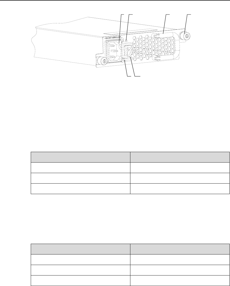
II. DC power module
For DC power supply, you must use a DC power module and DC power socket.
Table 1-27 DC Power supply specifications
Item DC power module
Rated voltage range -48 VDC to -60 VDC
Input voltage range -36 VDC to -72 VDC
Max power output 296 W
1.11.5 PoE Power Supply
When connected to a PoE power supply, the S7502 can supply power to remote PDs
such as IP phone sets and WLAN access points, through a card supporting the PoE
function.