
H3C S7502 Ethernet Switch Installation Manual
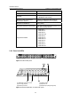
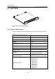
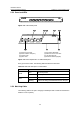
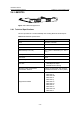
Table Of Contents
- 00-1Cover.pdf
- 01-Chapter 1 Product Overview.pdf
- 02-Chapter 2 Line Processing Units.pdf
- 03-Chapter 3 nstallation Preparations.pdf
- 04-Chapter 4 Hardware Installation.pdf
- Chapter 4 Hardware Installation
- 05-Chapter 5 System Commissioning.pdf
- 06-Chapter 6 Hardware Maintenance.pdf
- 07-Chapter 7 Software Maintenance.pdf
- Chapter 7 Software Maintenance
- 7.1 Introduction to Loading Approaches
- 7.2 Loading Software Locally through Boot Menu
- 7.3 Loading Software Remotely or Locally through Command Lines
- 7.4 Booting the Switch with Dual Images
- 7.5 Loading a Host Software Containing the Boot ROM File
- 7.6 Handling Loading Failure
- 7.7 Handling Password Loss
- Chapter 7 Software Maintenance
- 08-Chapter 8 Troubleshooting.pdf
- 09-Appendix A Lightning Protection.pdf
- 10-Appendix B AC Power Cables Used in Different Countries.pdf
Installation Manual
H3C S7502 Ethernet Switch Chapter 2 Line Processing Units
2-3
Every port has a green LED. The following table describes the LED state.
Table 2-2 LED state description of LS81FT48E
LED State Description
OFF
No link is present.
ON
A link is present
LINK/ACT
Blinking
Packets are being transmitted/received on the port.
2.2.3 Matching Cable
The matching cable to the port is category-5 twisted pair with a maximum transmission
distance of 100 m (328 ft).
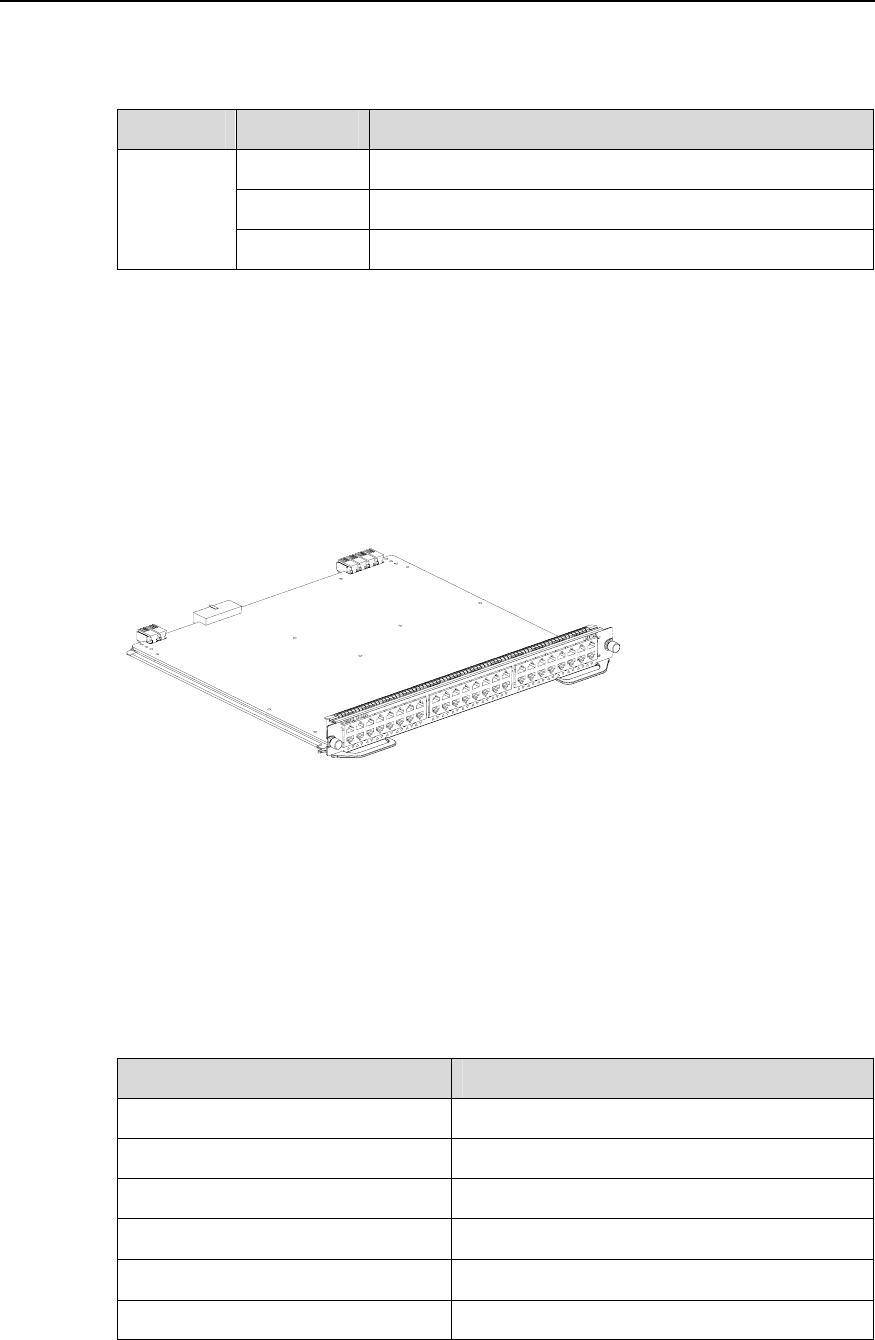
2.3 LS81FT48F
Figure 2-4 LS81FT48F appearance
2.3.1 Technical Specifications
This LPU provides 48 × 10/100 Mbps auto-sensing Ethernet electrical port service
channels. And all the ports support PoE, that is, to implement remote power supply to
PDs through Ethernet twisted pair cables.
Table 2-3 LS81FT48F specifications
Item LS81FT48F
CPU MPC8241, 200 MHz
Boot ROM 512 KB
SDRAM 128 MB
Dimensions (H × W x D)
40.1 × 376.7 × 354.5 mm (1.6 × 14.8 × 14 in.)
Max power consumption 35 W
Connector RJ-45