
H3C S7502 Ethernet Switch Installation Manual
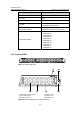
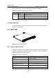
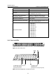
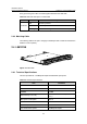
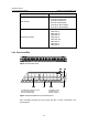
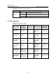
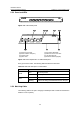
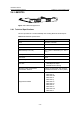
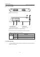
Table Of Contents
- 00-1Cover.pdf
- 01-Chapter 1 Product Overview.pdf
- 02-Chapter 2 Line Processing Units.pdf
- 03-Chapter 3 nstallation Preparations.pdf
- 04-Chapter 4 Hardware Installation.pdf
- Chapter 4 Hardware Installation
- 05-Chapter 5 System Commissioning.pdf
- 06-Chapter 6 Hardware Maintenance.pdf
- 07-Chapter 7 Software Maintenance.pdf
- Chapter 7 Software Maintenance
- 7.1 Introduction to Loading Approaches
- 7.2 Loading Software Locally through Boot Menu
- 7.3 Loading Software Remotely or Locally through Command Lines
- 7.4 Booting the Switch with Dual Images
- 7.5 Loading a Host Software Containing the Boot ROM File
- 7.6 Handling Loading Failure
- 7.7 Handling Password Loss
- Chapter 7 Software Maintenance
- 08-Chapter 8 Troubleshooting.pdf
- 09-Appendix A Lightning Protection.pdf
- 10-Appendix B AC Power Cables Used in Different Countries.pdf
Installation Manual
H3C S7502 Ethernet Switch Chapter 2 Line Processing Units
2-6
Item LS81FP48
SFP module
z SFP-FE-SX-MM1310-A
z SFP-FE-LX-SM1310-A
z SFP-FE-LH40-SM1310
z SFP-FE-LH80-SM1550
z SFP-FE-LX-SM1310-BIDI
z SFP-FE-LX-SM1550-BIDI
Supported standard
z IEEE 802.3
z IEEE 802.1p
z IEEE 802.1Q
z IEEE 802.1D
z IEEE 802.3x
z IEEE 802.3ad
z IEEE 802.1X
z IEEE 802.1s
z IEEE 802.1w
2.4.2 Panel and LEDs
Figure 2-8 LS81FP48 panel
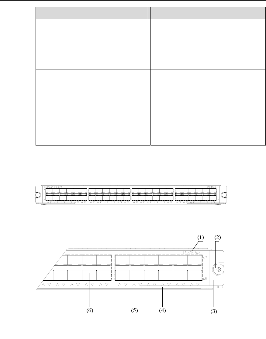
(1) Silkscreen of the LPU name (2) Captive screw
(3) LPU edge (Purple) (4) Ejector lever
(5) SFP interface LED (6) SFP interface
Figure 2-9 Partial amplification of LS81FP48 panel
Each 100 Mbps electrical port has a green LED with it, which is described in the
following table.