
H3C S7502 Ethernet Switch Installation Manual
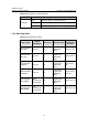
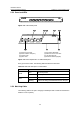
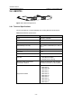
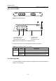
Table Of Contents
- 00-1Cover.pdf
- 01-Chapter 1 Product Overview.pdf
- 02-Chapter 2 Line Processing Units.pdf
- 03-Chapter 3 nstallation Preparations.pdf
- 04-Chapter 4 Hardware Installation.pdf
- Chapter 4 Hardware Installation
- 05-Chapter 5 System Commissioning.pdf
- 06-Chapter 6 Hardware Maintenance.pdf
- 07-Chapter 7 Software Maintenance.pdf
- Chapter 7 Software Maintenance
- 7.1 Introduction to Loading Approaches
- 7.2 Loading Software Locally through Boot Menu
- 7.3 Loading Software Remotely or Locally through Command Lines
- 7.4 Booting the Switch with Dual Images
- 7.5 Loading a Host Software Containing the Boot ROM File
- 7.6 Handling Loading Failure
- 7.7 Handling Password Loss
- Chapter 7 Software Maintenance
- 08-Chapter 8 Troubleshooting.pdf
- 09-Appendix A Lightning Protection.pdf
- 10-Appendix B AC Power Cables Used in Different Countries.pdf

Installation Manual
H3C S7502 Ethernet Switch Chapter 2 Line Processing Units
2-7
Table 2-6 Description of a LS81FP48 LED
LED State
OFF The link is down or no link presented.
ON The link is active.
LINK/ACT
Blinking Data is being transmitted/received through the port.
2.4.3 Matching Cable
Table 2-7 LS81FP48 port cables
SFP module
Central
wavelength
Connector Matching cable
Maximum
transmission
distance
SFP-FE-SX-M
M1310-A
1,310 nm LC
Multimode
optical fiber
cable
2 km (1.2 mi)
SFP-FE-LX-S
M1310-A
1,310 nm LC
9 µm/125 µm
single mode
optical fiber
cable
15 km (9.3 mi)
SFP-FE-LH40
-SM1310
1,310 nm LC
9 µm/125 µm
single mode
optical fiber
cable
40 km (24.9
mi)
SFP-FE-LH80
-SM1550
1,550 nm LC
9 µm/125 µm
single mode
optical fiber
cable
80 km (about
49.7 mi)
SFP-FE-LX-S
M1310-BIDI
1550
(receive)/1310
nm (transmit)
LC
9 9 µm/125 µm
single mode
optical fiber
cable
15 km (9.3 mi)
SFP-FE-LX-S
M1550-BIDI
1310
(transmit)/155
0nm (receive)
LC
9 µm/125 µm
single mode
optical fiber
cable
15 km (9.3 mi)