
H3C S7502 Ethernet Switch Installation Manual
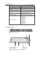
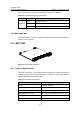
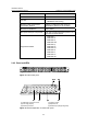
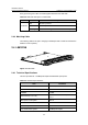
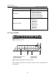
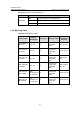
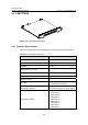
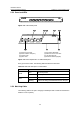
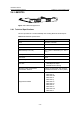
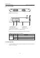
Table Of Contents
- 00-1Cover.pdf
- 01-Chapter 1 Product Overview.pdf
- 02-Chapter 2 Line Processing Units.pdf
- 03-Chapter 3 nstallation Preparations.pdf
- 04-Chapter 4 Hardware Installation.pdf
- Chapter 4 Hardware Installation
- 05-Chapter 5 System Commissioning.pdf
- 06-Chapter 6 Hardware Maintenance.pdf
- 07-Chapter 7 Software Maintenance.pdf
- Chapter 7 Software Maintenance
- 7.1 Introduction to Loading Approaches
- 7.2 Loading Software Locally through Boot Menu
- 7.3 Loading Software Remotely or Locally through Command Lines
- 7.4 Booting the Switch with Dual Images
- 7.5 Loading a Host Software Containing the Boot ROM File
- 7.6 Handling Loading Failure
- 7.7 Handling Password Loss
- Chapter 7 Software Maintenance
- 08-Chapter 8 Troubleshooting.pdf
- 09-Appendix A Lightning Protection.pdf
- 10-Appendix B AC Power Cables Used in Different Countries.pdf
Installation Manual
H3C S7502 Ethernet Switch Chapter 2 Line Processing Units
2-9
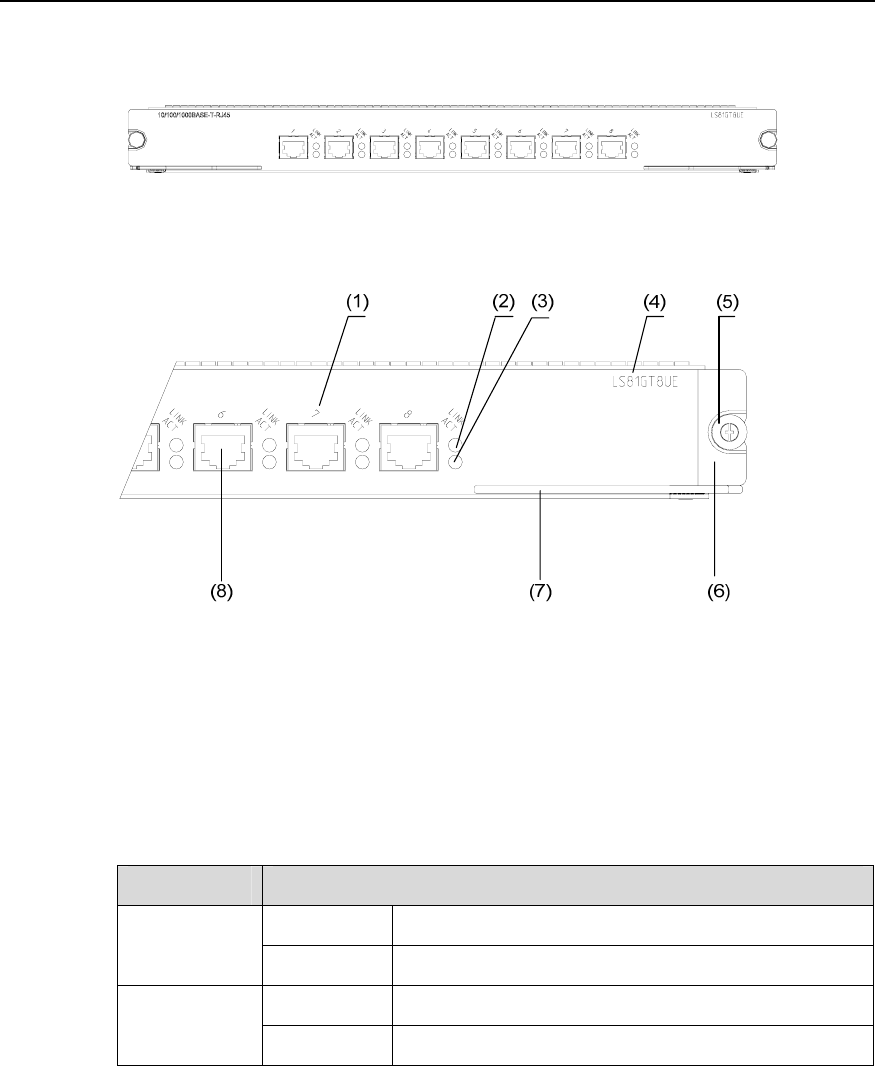
2.5.2 Panel and LEDs
Figure 2-11 LS81GT8UE panel
(1) Ethernet port number (2) Port status LED(LINK)
(3) Interface status LED (ACT) (4) Silkscreen of the LPU name
(5) Captive screw (6) LPU edge (Purple)
(7) Ejector lever (8) Ethernet interface (Gigabit)
Figure 2-12 Partial amplification of LS81GT8UE panel
Every port has two LEDs. The following table describes the LED state.
Table 2-9 LED state description of LS81GT8UE
LED State
OFF No link is present.
LINK
ON A link is present.
OFF No packets are transmitted/received on the port.
ACT
Blinking Packets are being transmitted/received on the port.
2.5.3 Matching Cable
The matching cable to the port is category-5 twisted pair with a maximum transmission
distance of 100 m (328 ft).