
H3C S7502 Ethernet Switch Installation Manual
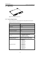
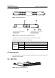
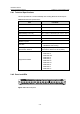
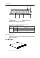
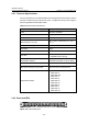
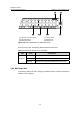
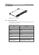
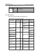
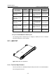
Table Of Contents
- 00-1Cover.pdf
- 01-Chapter 1 Product Overview.pdf
- 02-Chapter 2 Line Processing Units.pdf
- 03-Chapter 3 nstallation Preparations.pdf
- 04-Chapter 4 Hardware Installation.pdf
- Chapter 4 Hardware Installation
- 05-Chapter 5 System Commissioning.pdf
- 06-Chapter 6 Hardware Maintenance.pdf
- 07-Chapter 7 Software Maintenance.pdf
- Chapter 7 Software Maintenance
- 7.1 Introduction to Loading Approaches
- 7.2 Loading Software Locally through Boot Menu
- 7.3 Loading Software Remotely or Locally through Command Lines
- 7.4 Booting the Switch with Dual Images
- 7.5 Loading a Host Software Containing the Boot ROM File
- 7.6 Handling Loading Failure
- 7.7 Handling Password Loss
- Chapter 7 Software Maintenance
- 08-Chapter 8 Troubleshooting.pdf
- 09-Appendix A Lightning Protection.pdf
- 10-Appendix B AC Power Cables Used in Different Countries.pdf
Installation Manual
H3C S7502 Ethernet Switch Chapter 2 Line Processing Units
2-15
(1) Silkscreen of the LPU name (2) Captive screw
(3) LPU edge (Purple) (4) Ejector lever
(5) Ethernet port LED (6) Ethernet interface (Gigabit)
Figure 2-21 Partial amplification of LS81GT48 panel
Every port has a LED. The following table describes the LED state.
Table 2-15 LED state description of LS81GT48
LED State Description
Off
No link is present.
On
A link is present
LINK/ACT
Blinking
Packets are being transmitted/received on the port.
2.8.3 Matching Cable
The matching cable to the port is category-5 twisted pair with a maximum transmission
distance of 100 m (328 ft).
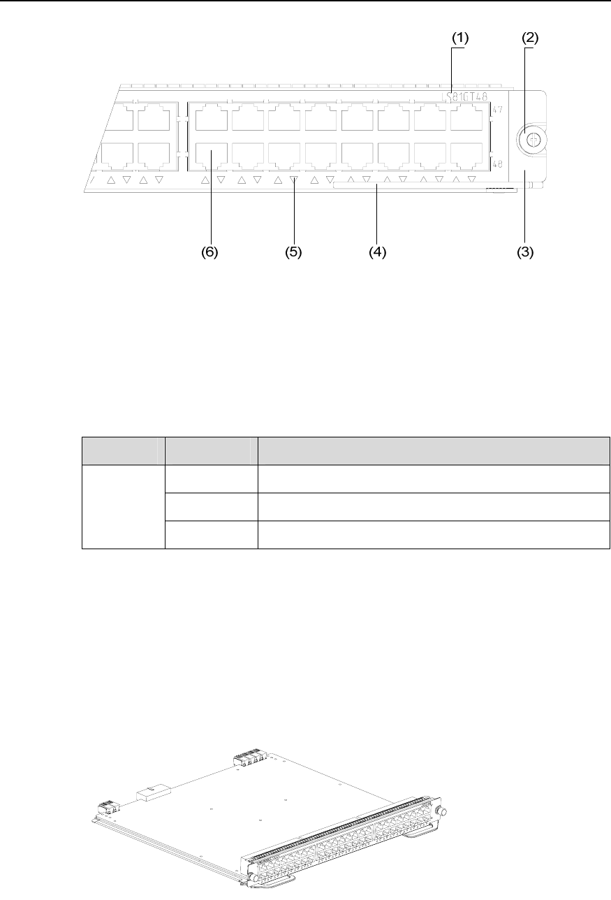
2.9 LS81GT48A
Figure 2-22 LS81GT48A appearance