
H3C S7502 Ethernet Switch Installation Manual
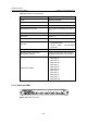
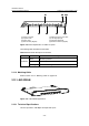
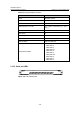
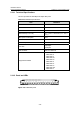
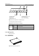

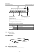
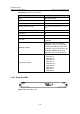
Table Of Contents
- 00-1Cover.pdf
- 01-Chapter 1 Product Overview.pdf
- 02-Chapter 2 Line Processing Units.pdf
- 03-Chapter 3 nstallation Preparations.pdf
- 04-Chapter 4 Hardware Installation.pdf
- Chapter 4 Hardware Installation
- 05-Chapter 5 System Commissioning.pdf
- 06-Chapter 6 Hardware Maintenance.pdf
- 07-Chapter 7 Software Maintenance.pdf
- Chapter 7 Software Maintenance
- 7.1 Introduction to Loading Approaches
- 7.2 Loading Software Locally through Boot Menu
- 7.3 Loading Software Remotely or Locally through Command Lines
- 7.4 Booting the Switch with Dual Images
- 7.5 Loading a Host Software Containing the Boot ROM File
- 7.6 Handling Loading Failure
- 7.7 Handling Password Loss
- Chapter 7 Software Maintenance
- 08-Chapter 8 Troubleshooting.pdf
- 09-Appendix A Lightning Protection.pdf
- 10-Appendix B AC Power Cables Used in Different Countries.pdf
Installation Manual
H3C S7502 Ethernet Switch Chapter 2 Line Processing Units
2-31
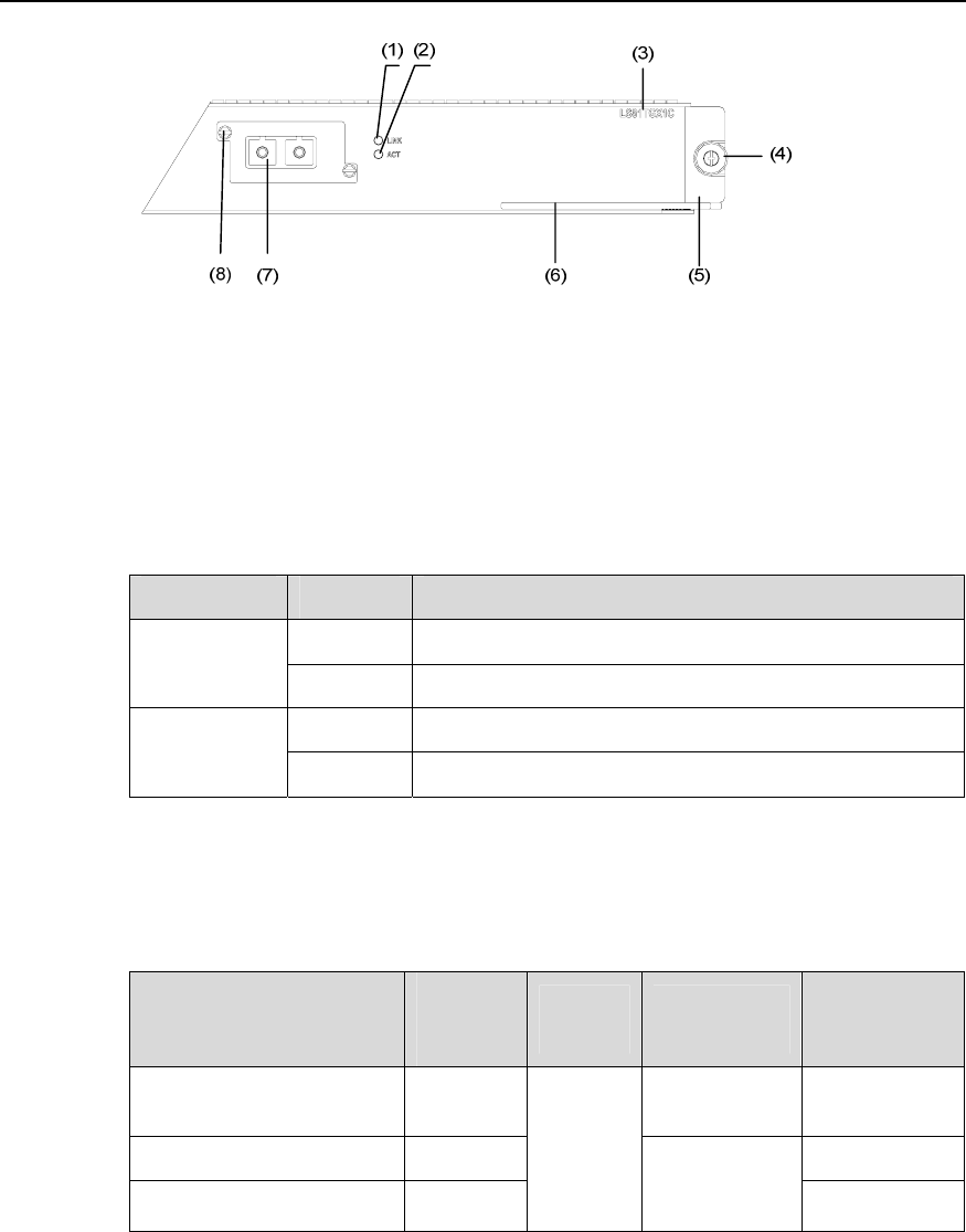
(1) Interface status LED (LINK) (2) Interface status LED (ACT)
(3) Silkscreen of the LPU name (4) Captive screw
(5) LPU edge (Green) (6) Ejector lever
(7) XENPAK interface (8) Captive screw
Figure 2-42 Partial amplification of LS81TGX1C panel
The following table describes the LED states of LS81TGX1C:
Table 2-30 LED state description of LS81TGX1C
LED State Description
OFF
No link is present.
LINK
ON
A link is present.
OFF
No packets are being transmitted/received on the port.
ACT
Blinking Packets are being transmitted/received on the port.
2.15.3 Matching Cable
Table 2-31 Matching cable available for LS81TGX1C
XENPAK module
Central
wavelen
gth
Connect
or
Matching
cable
Maximum
transmission
distance
XENPAK-SX-MM850 850 nm
Multimode
fiber
300 m (984 ft)
XENPAK-LX-SM1310 1310 nm 10 km (6 mi)
XENPAK-LH40-SM1550 1550 nm
SC
9µm/125µm
single mode
fiber
40 km (25 mi)