
H3C S7502 Ethernet Switch Installation Manual
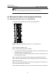
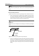
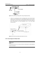
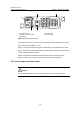
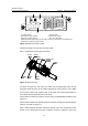
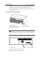
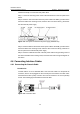
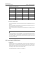
Table Of Contents
- 00-1Cover.pdf
- 01-Chapter 1 Product Overview.pdf
- 02-Chapter 2 Line Processing Units.pdf
- 03-Chapter 3 nstallation Preparations.pdf
- 04-Chapter 4 Hardware Installation.pdf
- Chapter 4 Hardware Installation
- 05-Chapter 5 System Commissioning.pdf
- 06-Chapter 6 Hardware Maintenance.pdf
- 07-Chapter 7 Software Maintenance.pdf
- Chapter 7 Software Maintenance
- 7.1 Introduction to Loading Approaches
- 7.2 Loading Software Locally through Boot Menu
- 7.3 Loading Software Remotely or Locally through Command Lines
- 7.4 Booting the Switch with Dual Images
- 7.5 Loading a Host Software Containing the Boot ROM File
- 7.6 Handling Loading Failure
- 7.7 Handling Password Loss
- Chapter 7 Software Maintenance
- 08-Chapter 8 Troubleshooting.pdf
- 09-Appendix A Lightning Protection.pdf
- 10-Appendix B AC Power Cables Used in Different Countries.pdf
Installation Manual
H3C S7502 Ethernet Switch Chapter 4 Hardware Installation
4-6
(1)
(2) (3)
(4)(5)
(1) AC input socket (2) Power LED
(3) Handle of power module (4) Power switch
(5) Bail latch
Figure 4-6 S7502 power module
The power module has AC input socket with bail latch and a power LED on its front
panel (The LED is described in 6.1.2).
Step 1: Pull up the bail latch to the right. The bail latch is on the left side of the panel.
Step 2: Insert the AC power cable which is shipped with the switch into the AC input
socket of the power supply module.
Step 3: Push back the bail latch to keep the power cable from being removed.
Step 4: Insert the other end of the power cable into the site power socket.
4.5.3 Connecting the DC Power Cable
Caution:
Power off all the related parts of the switch before connecting DC power cable.