
H3C S7502 Ethernet Switch Installation Manual
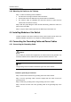
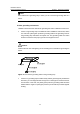
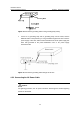
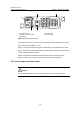
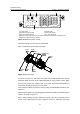
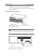
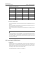
Table Of Contents
- 00-1Cover.pdf
- 01-Chapter 1 Product Overview.pdf
- 02-Chapter 2 Line Processing Units.pdf
- 03-Chapter 3 nstallation Preparations.pdf
- 04-Chapter 4 Hardware Installation.pdf
- Chapter 4 Hardware Installation
- 05-Chapter 5 System Commissioning.pdf
- 06-Chapter 6 Hardware Maintenance.pdf
- 07-Chapter 7 Software Maintenance.pdf
- Chapter 7 Software Maintenance
- 7.1 Introduction to Loading Approaches
- 7.2 Loading Software Locally through Boot Menu
- 7.3 Loading Software Remotely or Locally through Command Lines
- 7.4 Booting the Switch with Dual Images
- 7.5 Loading a Host Software Containing the Boot ROM File
- 7.6 Handling Loading Failure
- 7.7 Handling Password Loss
- Chapter 7 Software Maintenance
- 08-Chapter 8 Troubleshooting.pdf
- 09-Appendix A Lightning Protection.pdf
- 10-Appendix B AC Power Cables Used in Different Countries.pdf
Installation Manual
H3C S7502 Ethernet Switch Chapter 4 Hardware Installation
4-7
PGNDRTN -48V
-48V 60V;15A
(1) (2)
(3)
(4)
(1) Power switch (2) Power LED
(3) Handle of power module (4) DC power socket
RTN: -48 V working ground -48V: -48 V DC power
PGND: protection ground (You do not need to connect it because it is connected to the
chassis from inside the power module).
Figure 4-7 S7502 DC power module
Follow these steps to connect the DC power cable:
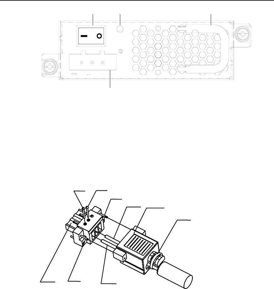
Step 1: Install the DC power plug components.
Dustproof cov er
Cable tie
Connector
Screw 4
Cable 2
Screw 1 Screw 2
Screw 3
Cable 1
Dustproof cov er
Cable tie
Connector
Screw 4
Cable 2
Screw 1 Screw 2
Screw 3
Cable 1
Figure 4-8 DC power plug
As shown in
Figure 4-8, first insert two cables into the appropriate holes through
dust-proof shield, and then fix the cables separately by using screws 1 and 2. Make
sure that the positive and negative ends of the cable are inserted appropriately in
accordance with the silkscreen print on the holes.
Fix the dust-proof shield by screws 3 and 4 by using a small flathead screwdriver, see
Figure 4-8.
Enlace the two cables to the polarizing key at the back of the dust-proof shield using the
cable tie, as shown in
Figure 4-8.
Step 2: After installing connector component, directly insert the component into DC
socket on the cabinet (Note that the component cannot be inserted in the wrong