
H3C S7502 Ethernet Switch Installation Manual
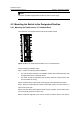
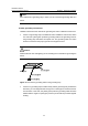
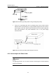
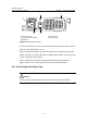
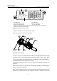
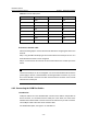
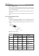
Table Of Contents
- 00-1Cover.pdf
- 01-Chapter 1 Product Overview.pdf
- 02-Chapter 2 Line Processing Units.pdf
- 03-Chapter 3 nstallation Preparations.pdf
- 04-Chapter 4 Hardware Installation.pdf
- Chapter 4 Hardware Installation
- 05-Chapter 5 System Commissioning.pdf
- 06-Chapter 6 Hardware Maintenance.pdf
- 07-Chapter 7 Software Maintenance.pdf
- Chapter 7 Software Maintenance
- 7.1 Introduction to Loading Approaches
- 7.2 Loading Software Locally through Boot Menu
- 7.3 Loading Software Remotely or Locally through Command Lines
- 7.4 Booting the Switch with Dual Images
- 7.5 Loading a Host Software Containing the Boot ROM File
- 7.6 Handling Loading Failure
- 7.7 Handling Password Loss
- Chapter 7 Software Maintenance
- 08-Chapter 8 Troubleshooting.pdf
- 09-Appendix A Lightning Protection.pdf
- 10-Appendix B AC Power Cables Used in Different Countries.pdf
Installation Manual
H3C S7502 Ethernet Switch Chapter 4 Hardware Installation
4-8
direction), and then fix the screws 1 and 2 carried by the connector itself to the
appropriate holes on the cabinet socket using a small flathead screwdriver.
Step 3: Check whether the power LED is ON. If the LED is ON, it indicates the power
cable is properly connected.
4.5.4 Connecting the PoE Power Cable
(a) AC power input socket (b) DC power output
(c) RS232 and RS485 interfaces (d) Chassis grounding point
Figure 4-9 Appearance of the PSE
Note:
For the method of installing the PSE2500-A3, see the related manual shipped with the
switch.
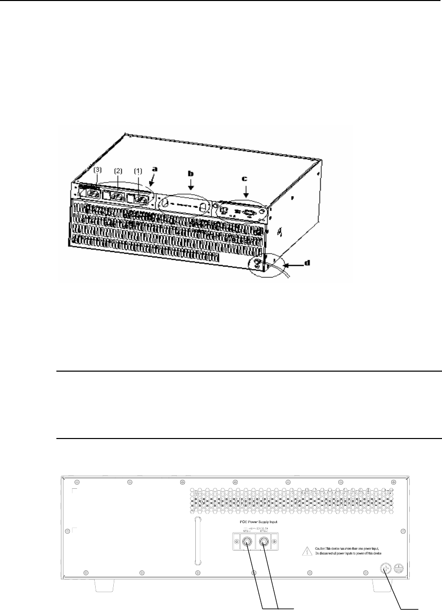
(1)(2)(3)
(1) Grounding screw (2) RTN(+) terminal of of PoE power supply
input
(3) NEG(-) terminal of PoE power supply input
Figure 4-10 Rear view of an S7502 PoE chassis