
H3C S7502 Ethernet Switch Installation Manual
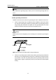
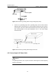
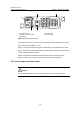
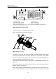
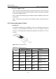
Table Of Contents
- 00-1Cover.pdf
- 01-Chapter 1 Product Overview.pdf
- 02-Chapter 2 Line Processing Units.pdf
- 03-Chapter 3 nstallation Preparations.pdf
- 04-Chapter 4 Hardware Installation.pdf
- Chapter 4 Hardware Installation
- 05-Chapter 5 System Commissioning.pdf
- 06-Chapter 6 Hardware Maintenance.pdf
- 07-Chapter 7 Software Maintenance.pdf
- Chapter 7 Software Maintenance
- 7.1 Introduction to Loading Approaches
- 7.2 Loading Software Locally through Boot Menu
- 7.3 Loading Software Remotely or Locally through Command Lines
- 7.4 Booting the Switch with Dual Images
- 7.5 Loading a Host Software Containing the Boot ROM File
- 7.6 Handling Loading Failure
- 7.7 Handling Password Loss
- Chapter 7 Software Maintenance
- 08-Chapter 8 Troubleshooting.pdf
- 09-Appendix A Lightning Protection.pdf
- 10-Appendix B AC Power Cables Used in Different Countries.pdf
Installation Manual
H3C S7502 Ethernet Switch Chapter 4 Hardware Installation
4-9
Follow these steps to connect the PoE power cable:
Step 1: Loosen the mounting screw of the PoE terminal block on the rear panel of the
switch.
Step 2: Insert the -48V OT terminal of the DC power cable to the NEG (-) terminal of the
switch and fasten the mounting screw; insert the other end to the NEG (-) terminal of
the external PoE power supply.
Figure 4-11 Rear panel of external PoE power supply (PSE2500-A3)
Step 3: Insert the GND OT terminal of the DC power cable to the RTN(+) terminal of the
switch and fasten the mounting screw; insert the other end to the RTN(+) terminal on
the rear panel of the external PoE power supply.
Step 4: Insert the PGND OT terminal of the DC power cable to the grounding screw of
the switch and fasten the mounting screw; insert the other end to the grounding bar for
the switch.
4.6 Connecting Interface Cables
4.6.1 Connecting the Console Cable
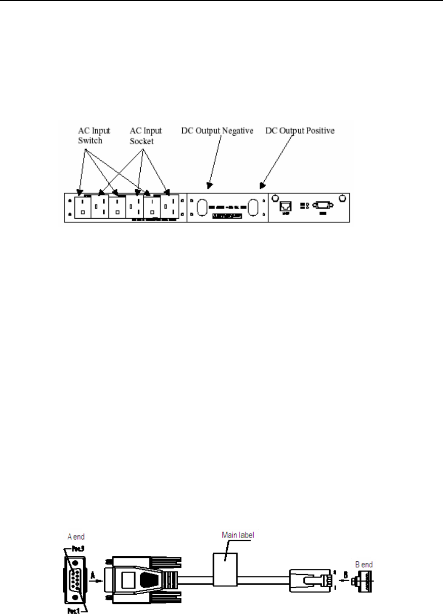
I. Introduction
Console cable is an 8-core shielded cable. One end of the cable is a crimped RJ-45
connector, which is to be plugged into the Console port of the switch. The other end is
furnished with a DB-9 (male) connector and can be inserted to the 9-core (female)
socket. The following figure illustrates the Console cable.
Figure 4-12 A Console cable