
H3C S7502 Ethernet Switch Installation Manual
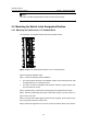
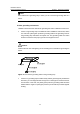
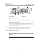
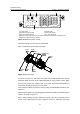
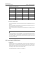
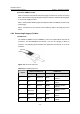
Table Of Contents
- 00-1Cover.pdf
- 01-Chapter 1 Product Overview.pdf
- 02-Chapter 2 Line Processing Units.pdf
- 03-Chapter 3 nstallation Preparations.pdf
- 04-Chapter 4 Hardware Installation.pdf
- Chapter 4 Hardware Installation
- 05-Chapter 5 System Commissioning.pdf
- 06-Chapter 6 Hardware Maintenance.pdf
- 07-Chapter 7 Software Maintenance.pdf
- Chapter 7 Software Maintenance
- 7.1 Introduction to Loading Approaches
- 7.2 Loading Software Locally through Boot Menu
- 7.3 Loading Software Remotely or Locally through Command Lines
- 7.4 Booting the Switch with Dual Images
- 7.5 Loading a Host Software Containing the Boot ROM File
- 7.6 Handling Loading Failure
- 7.7 Handling Password Loss
- Chapter 7 Software Maintenance
- 08-Chapter 8 Troubleshooting.pdf
- 09-Appendix A Lightning Protection.pdf
- 10-Appendix B AC Power Cables Used in Different Countries.pdf
Installation Manual
H3C S7502 Ethernet Switch Chapter 4 Hardware Installation
4-11
II. Connect COM Port Cable
When connected to the external PoE power supply, the switch can monitor the running
state of the external PoE power supply through the COM port. Take the following steps
to connect the COM port cable:
Step 1: Insert the DB-9 female plug of the COM port cable to the RS232 port of the PoE
power supply.
Step 2: Connect the RJ-45 connector of the COM port cable to the COM port of the
switch.
4.6.3 Connecting Category-5 Cables
I. Introduction
The 10Base-T/100Base-TX and 1000Base-T ports of an S7502 switch match RJ-45
connectors, and are MDI/MDIX auto-sensing. You can use category-5 cables to
connect it. The following figure illustrates the appearance and pinouts of an RJ-45
connector.
PIN #8
PIN #1
Figure 4-13 An RJ-45 connector
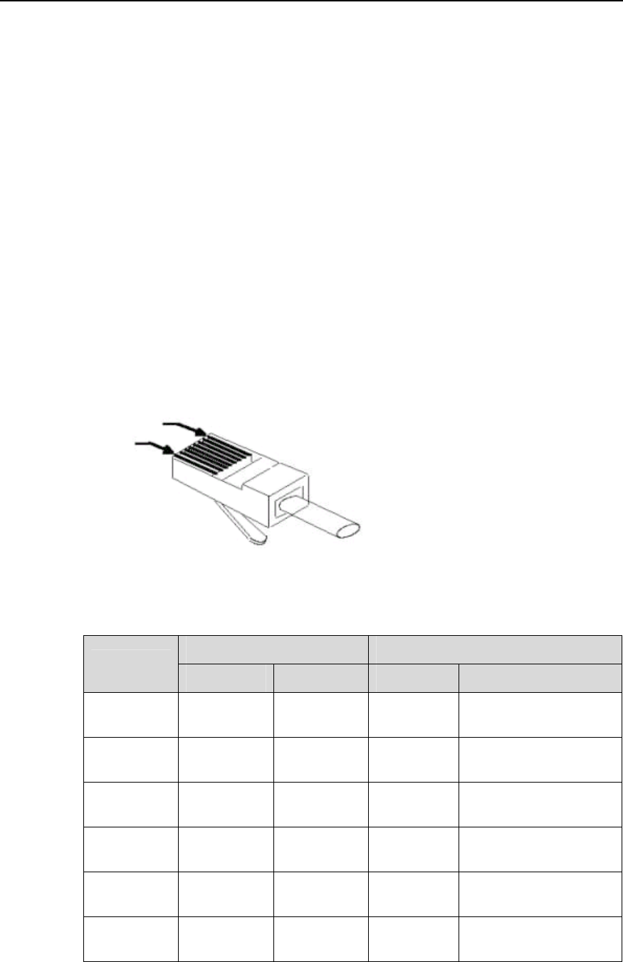
Table 4-2 RJ-45 MDI port pinout
10Base-T/100Base-TX 1000Base-T
Pinout
Signal Function Signal Function
1 Tx+ Outbound
BIDA+
Bi-directional data
cable A+
2 Tx- Outbound
BIDA-
Bi-directional data
cable A-
3 Rx+ Inbound
BIDB+
Bi-directional data
cable B+
4 Reserved
— BIDC+
Bi-directional data
cable C+
5 Reserved
— BIDC-
Bi-directional data
cable C-
6 Rx- Inbound
BIDB-
Bi-directional data
cable B-