
H3C S7502 Ethernet Switch Installation Manual
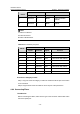
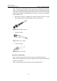
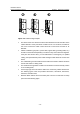
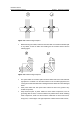
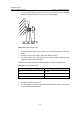

Table Of Contents
- 00-1Cover.pdf
- 01-Chapter 1 Product Overview.pdf
- 02-Chapter 2 Line Processing Units.pdf
- 03-Chapter 3 nstallation Preparations.pdf
- 04-Chapter 4 Hardware Installation.pdf
- Chapter 4 Hardware Installation
- 05-Chapter 5 System Commissioning.pdf
- 06-Chapter 6 Hardware Maintenance.pdf
- 07-Chapter 7 Software Maintenance.pdf
- Chapter 7 Software Maintenance
- 7.1 Introduction to Loading Approaches
- 7.2 Loading Software Locally through Boot Menu
- 7.3 Loading Software Remotely or Locally through Command Lines
- 7.4 Booting the Switch with Dual Images
- 7.5 Loading a Host Software Containing the Boot ROM File
- 7.6 Handling Loading Failure
- 7.7 Handling Password Loss
- Chapter 7 Software Maintenance
- 08-Chapter 8 Troubleshooting.pdf
- 09-Appendix A Lightning Protection.pdf
- 10-Appendix B AC Power Cables Used in Different Countries.pdf

Installation Manual
H3C S7502 Ethernet Switch Chapter 4 Hardware Installation
4-12
10Base-T/100Base-TX 1000Base-T
Pinout
Signal Function Signal Function
7 Reserved
— BIDD+
Bi-directional data
cable D+
8 Reserved
— BIDD-
Bi-directional data
cable D-
Note:
Tx refers to Outbound.
Rx refers to Inbound.
BI refers to Bi-directional.
Table 4-3 RJ-45 MDI-X port pinout
10Base-T/100Base-TX 1000Base-T
Pinout
Signal Function Signal Function
1 Rx+ Inbound
BIDB+ Bi-directional data cable B+
2 Rx- Inbound
BIDB- Bi-directional data cable B-
3 Tx+ Outbound
BIDA+ Bi-directional data cable A+
4 Reserved
— BIDD+ Bi-directional data cable D+
5 Reserved
— BIDD- Bi-directional data cable D-
6 Tx- Outbound
BIDA- Bi-directional data cable A-
7 Reserved
— BIDC+ Bi-directional data cable C+
8 Reserved
— BIDC- Bi-directional data cable C-
II. Connect a Category-5 cable
Step 1: Plug one end of the category-5 cable into an Ethernet RJ-45 jack of the switch
to be connected.
Step 2: Plug the other end of the cable into an RJ-45 port of the peer device.
4.6.4 Connecting Fibers
I. Introduction
Before connecting the fibers, make sure the type of the connector and the fiber match
that of the optical port.