
H3C S7502 Ethernet Switch Installation Manual
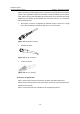
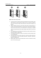
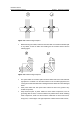
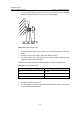
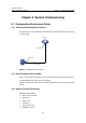
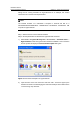
Table Of Contents
- 00-1Cover.pdf
- 01-Chapter 1 Product Overview.pdf
- 02-Chapter 2 Line Processing Units.pdf
- 03-Chapter 3 nstallation Preparations.pdf
- 04-Chapter 4 Hardware Installation.pdf
- Chapter 4 Hardware Installation
- 05-Chapter 5 System Commissioning.pdf
- 06-Chapter 6 Hardware Maintenance.pdf
- 07-Chapter 7 Software Maintenance.pdf
- Chapter 7 Software Maintenance
- 7.1 Introduction to Loading Approaches
- 7.2 Loading Software Locally through Boot Menu
- 7.3 Loading Software Remotely or Locally through Command Lines
- 7.4 Booting the Switch with Dual Images
- 7.5 Loading a Host Software Containing the Boot ROM File
- 7.6 Handling Loading Failure
- 7.7 Handling Password Loss
- Chapter 7 Software Maintenance
- 08-Chapter 8 Troubleshooting.pdf
- 09-Appendix A Lightning Protection.pdf
- 10-Appendix B AC Power Cables Used in Different Countries.pdf
Installation Manual
H3C S7502 Ethernet Switch Chapter 4 Hardware Installation
4-13
Fiber connectors are indispensable passive components in optical fiber communication
system. Their application enables the removable connection between optical channel,
which makes optical system debugging and maintenance more convenient and transit
dispatching more flexible. Among multiple fiber connectors, only SC, LC, and MT-RJ
will be introduced here.
z MT-RJ fiber connector: It integrates two channels of light sources into a single
fiber, which reduces the actual ports that are in use of a connector.
Figure 4-14 An MT-RJ connector
z SC fiber connector
Figure 4-15 An SC connector
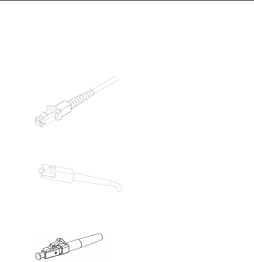
z LC fiber connector
Figure 4-16 An LC connector
II. Connect an optical fiber
Step 1: Remove the protective cap from the connector and clean the fiber end.
Step 2: Remove the optical port cover of the switch. Insert one end of the fiber into the
optical port of the switch.
Step 3: Connect the other end of the fiber to the corresponding device.