
H3C S7502 Ethernet Switch Installation Manual
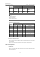
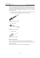
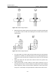
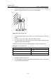
Table Of Contents
- 00-1Cover.pdf
- 01-Chapter 1 Product Overview.pdf
- 02-Chapter 2 Line Processing Units.pdf
- 03-Chapter 3 nstallation Preparations.pdf
- 04-Chapter 4 Hardware Installation.pdf
- Chapter 4 Hardware Installation
- 05-Chapter 5 System Commissioning.pdf
- 06-Chapter 6 Hardware Maintenance.pdf
- 07-Chapter 7 Software Maintenance.pdf
- Chapter 7 Software Maintenance
- 7.1 Introduction to Loading Approaches
- 7.2 Loading Software Locally through Boot Menu
- 7.3 Loading Software Remotely or Locally through Command Lines
- 7.4 Booting the Switch with Dual Images
- 7.5 Loading a Host Software Containing the Boot ROM File
- 7.6 Handling Loading Failure
- 7.7 Handling Password Loss
- Chapter 7 Software Maintenance
- 08-Chapter 8 Troubleshooting.pdf
- 09-Appendix A Lightning Protection.pdf
- 10-Appendix B AC Power Cables Used in Different Countries.pdf
Installation Manual
H3C S7502 Ethernet Switch Chapter 4 Hardware Installation
4-15
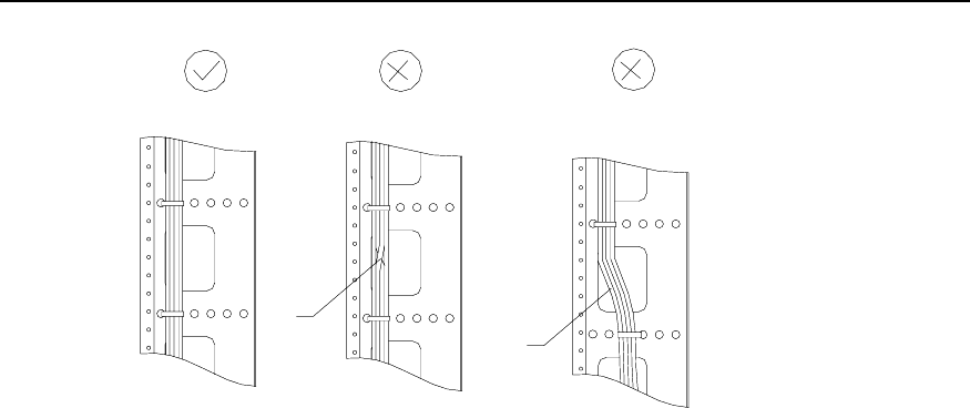
Twisting
Bending
Twisting
Bending
Figure 4-17 Cable binding example I
z The radius of the curve at which a cable is bent should be no less than twice of the
cable’s diameter. At the point where a cable runs out of a connector, the radius of
the curve at which the cable is bent should be no less than five times of its
diameter.
z Cables of different type (that is, power cable, signal cable, grounding cable, etc.)
should run and be bound separately in a cabinet. They cannot be bound together.
If they are close to each other, you can cable them in a crossing way. For parallel
cabling, the space between power cable and signal cable should be no less than
30mm;
z The cable binding rack and cable channel inside and outside a cabinet should be
smooth and stretch no sharp points.
z The metal hole through which a cable runs should have a smooth and fully surface
or an insulating bush;
z Use the right type of ties to bind the cables. Do not bind any cables with tied ties.
The following types of ties are provided: 100*2.5mm, 150*3.6mm, 300*3.6mm,
530*9mm, and 580*13mm;
z Bind the cables with ties and cut the extra parts. Trim the cut and leave no sharp
points. See the following figure: