
H3C S7502 Ethernet Switch Installation Manual
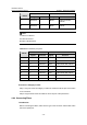
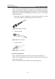
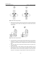
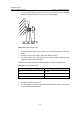
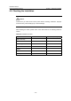
Table Of Contents
- 00-1Cover.pdf
- 01-Chapter 1 Product Overview.pdf
- 02-Chapter 2 Line Processing Units.pdf
- 03-Chapter 3 nstallation Preparations.pdf
- 04-Chapter 4 Hardware Installation.pdf
- Chapter 4 Hardware Installation
- 05-Chapter 5 System Commissioning.pdf
- 06-Chapter 6 Hardware Maintenance.pdf
- 07-Chapter 7 Software Maintenance.pdf
- Chapter 7 Software Maintenance
- 7.1 Introduction to Loading Approaches
- 7.2 Loading Software Locally through Boot Menu
- 7.3 Loading Software Remotely or Locally through Command Lines
- 7.4 Booting the Switch with Dual Images
- 7.5 Loading a Host Software Containing the Boot ROM File
- 7.6 Handling Loading Failure
- 7.7 Handling Password Loss
- Chapter 7 Software Maintenance
- 08-Chapter 8 Troubleshooting.pdf
- 09-Appendix A Lightning Protection.pdf
- 10-Appendix B AC Power Cables Used in Different Countries.pdf
Installation Manual
H3C S7502 Ethernet Switch Chapter 4 Hardware Installation
4-17
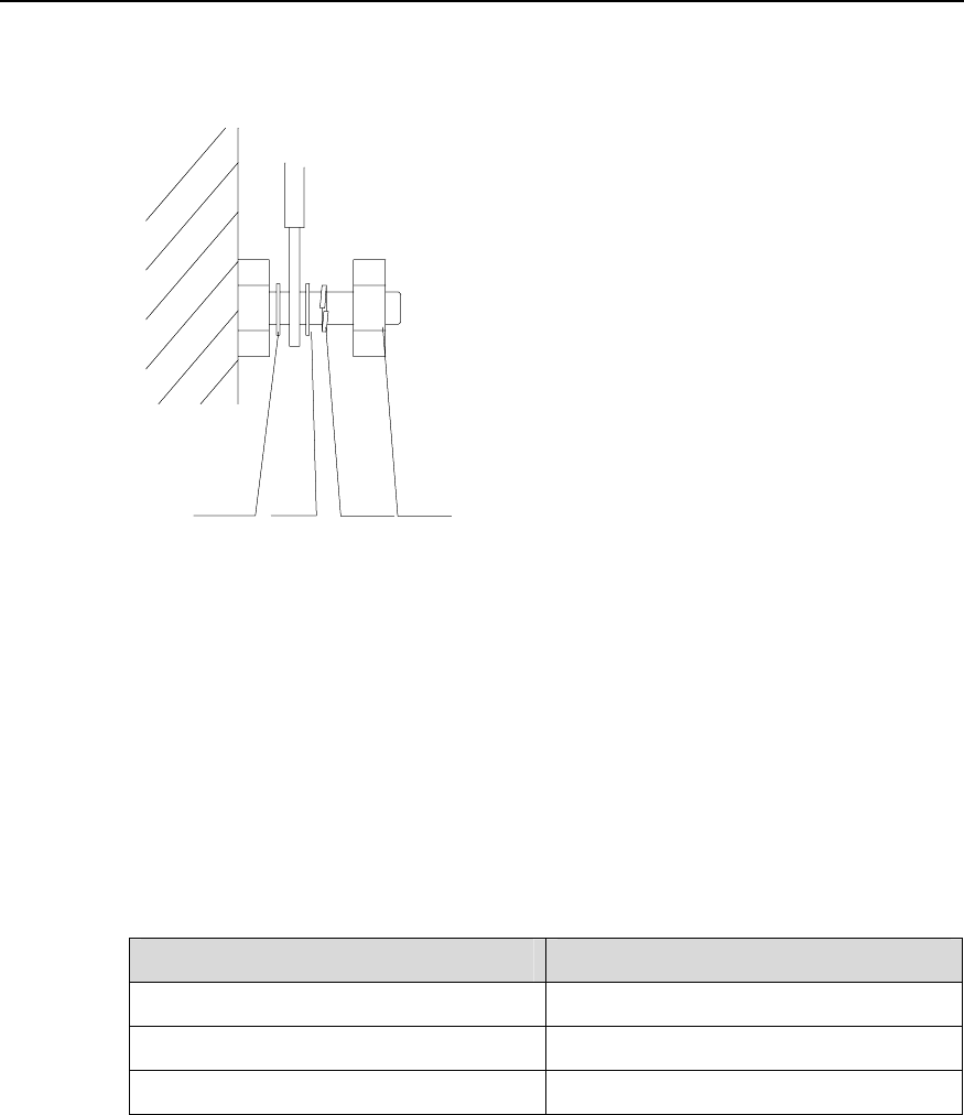
z For the cable terminals fixed with screw thread, the screws or nuts should be
fastened and prevented from loosing. See the following figure;
Flat
washer
Flat
washer
Spring
washer
Nut
Flat
washer
Flat
washer
Spring
washer
Nut
Figure 4-20 Cable fixing example
z Fix the terminal of harder power cables to free the terminal and the cable from
stress;
z No tapping screw can be used to fasten the cabling terminals;
z The power cables of the same type and in the same direction should be bound
together and kept clean and straight;
Follow the parameters defined in the following table for binding cables with ties.
Table 4-4 Tie-binding parameters
Cable bundle diameter (mm) Space between bundles (mm)
10 80~150
10~30 150~200
30 200~300
z No cable or bundle can tie a knot;
z The metal parts of crimping cold-pressed terminal blocks (such as air switch)
cannot stretch beyond the blocks.