HP 12500-CMW710-R7129 Release Notes © Copyright 2013 Hewlett-Packard Development Company, L.P. The information contained herein is subject to change without notice. The only warranties for HP products and services are set forth in the express warranty statements accompanying such products and services. Nothing herein should be construed as constituting an additional warranty. HP shall not be liable for technical or editorial errors or omissions contained herein.
Contents Version information ··················································································································································································1 Version number ·····························································································································································································1 Version history ·················································································
List of Tables Table 1 Version history .................................................................................................................................................................... 1 Table 2 HP 12500 product family matrix ................................................................................................................................. 1 Table 3 Hardware and software compatibility matrix ....................................................................................
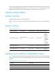
This document describes features, restrictions and guidelines, open problems, and workarounds for version 12500-CMW710-R7129. Before you use this version in a live network, back up the configuration and test the version to avoid software upgrade affecting your live network. Version information Version number Comware Software, Version 7.1.034, Release 7129 Note: You can see the version number with the command display version in any view. Please see Note①.
CAUTION: To perform a correct upgrade, use Table 3 to verify the hardware and software compatibility before performing an upgrade. Table 3 Hardware and software compatibility matrix Item Specifications Product family HP 12500 Switch Series Hardware platform 12504/12508/12518 Memory MPUs: 4 GB Flash 128 MB (Each MPU must have an HP certified 1-GB CF card.) MPUs: BootWare 2.19 or above. See Note②. Boot ROM version OAM CPUs and interface cards: BootWare2.12 or above. See Note.
Number of Cpld: 2 Cpld 0: SoftWare : 005 Cpld 1: SoftWare PowChipA : 005 : 005 CpuCard Type : LSR1CPA PCB : Ver.C Number of Cpld: 1 Cpld 0: SoftWare BootRom : 001 : 2.12 -------- Note③ Mbus card Type : LSR1MBCB Software : 115 PCB : Ver.B LST1GT48LEC1 4: --------Note⑤ uptime is 0 weeks, 0 days, 0 hours, 2 minutes Last reboot reason : Other 1024 Mbytes SDRAM 0 Kbytes NVRAM Memory Type : LST1GT48LEC1 Software : 12500-CMW710-R7129 PCB : Ver.
BootRom : 2.12 --------Note④ Software : 12500-CMW710-R7129 PCB : Ver.A Board Cpu: Number of Cpld: 1 Cpld 0: SoftWare PowChipA : 001 : 001 Upgrading restrictions and guidelines None. Hardware feature updates 12500-CMW710-R7129 None. 12500-CMW710-R7128 None. 12500-CMW710-R7125 None. Software feature and command updates For more information about the software feature and command update history, see HP 12500-CMW710-R7129 Release Notes (Software Feature Changes).
Item MIB file Module Description Modified None None None 12500-CMW710-R7125 New None None None Modified None None None Operation changes Operation changes in 12500-CMW710-R7129 Adding an MDC configuration restriction error message The R7129 release introduced an error message to show that executing the location slot command fails because the maximum number of MDCs associated with the specified interface card is exceeded.
Restrictions and cautions Restriction 1 [Configuration management] Do not perform any configuration within one minute before an active/standby switchover because the configurations might be lost after the switchover. Restriction 2 [Tunnel] IPv6 addresses that begin with 2002 can only be used on 6to4 tunnels. Use of such addresses on other types of tunnels causes forwarding problems. Restriction 3 [QoS] Make sure the CBS and EBS configured for CAR are larger than the maximum packet size.
Restriction 12 [IRF] The BFD MAD VLAN must not have physical loops or be configured for any services other than BFD MAD. Restriction 13 [Enhanced IRF] In enhanced IRF mode, the following requirements must be met: Each IRF member switch must have two MPUs. The IRF fabric uses a ring topology. The downstream switch must have one link to each IRF member switch and aggregate these links in an aggregation group.
Open problems and workarounds None. List of resolved problems Resolved problems in 12500-CMW710-R7129 TCD003126 Symptom: On an IRF fabric that acts as an ED device in an EVI network, if an EVI link goes down and then recovers because of IGP flapping when a master/subordinate switchover occurs, the ED device might not send its MAC address to the peer device within three minutes. As a result, the peer device cannot learn the MAC address and fails to communicate with the ED device.
Resolved problems in 12500-CMW710-R7125 None. Related documentation Documentation set HP 12500 Routing Switch Series Installation Guide HP 12500 Routing Switch Series Configuration Guides HP 12500 Routing Switch Series Command References Obtaining documentation To find related documents, browse to the Manuals page of the HP Business Support Center website: http://www.hp.com/support/manuals Contacting HP For worldwide technical support information, see the HP support website: http://www.hp.
Appendix A Feature list Hardware features Table 5 12500 series hardware features Item 12504 12508 12518 Dimensions (W × H ×D) 442 × 442 × 708 mm (17.40 × 17.40 ×27.87 in) 442 × 975 × 740 mm (17.40 × 38.39 ×29.13 in.) 442 × 1686 × 740 mm (17.40 × 66.38 ×29.13 in.) 12504-AC: 12508-AC: 12518-AC: Net weight: 56.5 kg (124.56 lb) Net weight: 97.5 kg (214.95 lb) Net weight: 166.8 kg (367.72 lb) Full configuration: ≤ 100 kg (220.46 lb) Full configuration: ≤ 180 kg (396.
Item interfaces 12504 12508 12518 AUX 1 1 1 USB 1 1 1 Network management GE 1 1 1 Table 6 12500 hardware modules with minimum software release Item Switch chassis MPU cards Ethernet interface cards HP code Description Minimum Software Release JC654A HP 12504 AC Switch Chassis R1728P02 JC655A HP 12504 DC Switch Chassis R1728P02 JF430C HP 12518 AC Switch Chassis R1726 JC653A HP 12518 DC Switch Chassis R1726 JF431C HP 12508 AC Switch Chassis R1726 JC652A HP 12508 DC Swit
Item Switch fabric modules Transceiver modules and cables HP code Description Minimum Software Release JC476B HP 12500 32-port 10-GbE SFP+ REC Module R1726 JC811A HP 12500 48-port GbE SFP LEC TAA-compliant Module R1726 JC809A HP 12500 48-port Gig-T LEC TAA-compliant Module R1726 JC818A HP 12500 48-port GbE SFP LEF TAA-compliant Module R1726 JC813A HP 12500 8-port 10-GbE SFP+ LEC TAA-compliant Module R1726 JC817A HP 12500 8-port 10-GbE SFP+ LEF TAA-compliant Module R1726 JC812A HP 12
Item HP code Description Minimum Software Release JD063B HP X125 1G SFP LC LH70 Transceiver R1238P02 JD109A HP X170 1G SFP LC LH70 1550 Transceiver R1238P02 JD110A HP X170 1G SFP LC LH70 1570 Transceiver R1238P02 JD111A HP X170 1G SFP LC LH70 1590 Transceiver R1238P02 JD112A HP X170 1G SFP LC LH70 1610 Transceiver R1238P02 JD119B HP X120 1G SFP LC LX Transceiver R1238P02 JD098B HP X120 1G SFP LC BX 10-U Transceiver R1238P02 JD099B HP X120 1G SFP LC BX 10-D Transceiver R1238P02 JD
upgraded from 1 GB to 4 GB of SDRAM by using two memory upgrade kits (2 x JC609A). If required, 1 GB CF cards (JC684A) are available for purchase. If an upgraded JC072A needs to be returned for repair, be sure to retain the upgrade parts for use in the replacement unit. Due to physical memory limits, interface cards with 512 MB memory do not support ISSU, and the interfaces on each of these interface cards can be assigned to only one MDC.
HP code JC068A JC064A Description HP 8-Port 10-GbE XFP 12500 Module HP 32-Port 10GE SFP+ 12500 Module (REB) ISSU MDC Not Supported Supported with limitation: The interfaces on one card can be assigned to only one MDC Not Supported Supported with limitation: The interfaces on one card can be assigned to only one MDC JC476A HP 32-port 10GbE SFP+ REC 12500 Module Not Supported Supported with limitation: The interfaces on one card can be assigned to only one MDC JC073B HP 12500 8-port 10-GbE XF
HP code Description ISSU MDC JC817A HP 12500 8-port 10-GbE SFP+ LEF TAA-compliant Module Supported Supported JC812A HP 12500 32-port 10-GbE SFP+ REC TAA-compliant Module Supported Supported Software features Table 8 12500 software features Category Link layer MAC address management Features Link aggregation, port isolation, port mirroring DLDP Limit on the number of learned MAC addresses Static MAC address configuration VLAN Port-based VLANs QinQ Basic QinQ IRF2—Up to four chassis MDC—Up t
Category Features Inbound/outbound ACLs ACL Basic/advanced/user-defined ACLs Port-based/VLAN/global ACLs TCP, UDP, RawIP, Ping, Traceroute Telnet, FTP, TFTP ICMPv4 IPv4 protocols DNS UDP Helper DHCP NTP ARP, ARP Proxy IPv4/IPv6 dual stack TCP6, UDP6, RawIP6, Pingv6, Traceroutev6 IPv6 Telnet, IPv6 FTP, IPv6 TFTP IPv6 DNS IPv6 protocols ICMPv6 VRRPv3 DHCPv6 ND PMTUD (IPv6) 6PE RIPv1/v2 OSPFv2 IPv4 routing protocols IS-IS BGPv4 Static routing/route policy/route recursion/policy based routing for IPv4
Category Features MPLS basic functions MPLS MPLS L3VPN VLL 6VPE Data packet attack defense Protocol packet attack defense Device security Attack detection Protocol packet protection Incoming/outgoing packet diagnosis Packet validity check URPF check Network security Packet filtering ARP attack defense SIP/SA consistency check Protocol-classification-based traffic limit Device management security User security Network user binding AAA SSH CLI-based device configuration through the console port Devi
Category Features Card hot swapping Switching fabric module redundancy Active/standby switchover Inline hot fix High availability GR VRRP, VRRPE BFD for VRRP/BGP/IS-IS/RIP/OSPF/static routing IP FRR ISSU Appendix B Upgrading software The software image files used on the 12500 switch series include the Comware images, BootWare image, MBUS image, power supply monitoring image, and fan monitoring image. Basic Comware images include the system image and the boot image.
If you are migrating from Comware V5 to Comware V7, use the separate .bin system and boot image files. If you are upgrading from one Comware V7 release to another, you can use the .ipe package file. The switch supports Comware image redundancy: main and backup. The switch always attempts to load the main Comware images at startup. If a main Comware image is not available or corrupted, the switch attempts to load the backup Comware images.
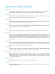
Figure 1 Console connection for local upgrade Upgrading from the CLI without using ISSU You can upgrade the Comware software from the CLI through TFTP or FTP. Using TFTP to upgrade software This section describes how to upgrade system software by using TFTP. Backing up the running system software image and configuration file 1. Use the save command in any view to save the running configuration. save The current configuration will be written to the device.
dir Directory of cfa0: 0 drw- - Sep 15 2012 14:32:26 diagfile 1 drw- - Sep 15 2012 14:32:26 2 -rw- 37137408 Sep 15 2012 14:26:38 main-boot.bin logfile 3 -rw- 62894080 Sep 15 2012 14:27:06 main-system.bin 4 -rw- 1694 Sep 15 2012 14:47:12 startup.cfg 1021808 KB total (864868 KB free) 3. Use the tftp put command in user view to upload the Comware images to the TFTP server. tftp 192.168.1.1 put main-boot.bin % Total 100 35.
Add images to target slot. The specified file list will be used as the main startup software images at the next reboot on slot 0. 3. Perform the display boot-loader command in user view to verify that the file has been loaded. display boot-loader Software images on slot 0: Current software images: cfa0:/main-boot.bin cfa0:/main-system.bin Main startup software images: cfa0:/update-boot.bin cfa0:/update-system.bin Backup startup software images: None 4.
2. Use the dir command in user view to identify the startup Comware software images and configuration file and verify that the CF card has enough space for the new software images. dir Directory of cfa0: 0 drw- - Sep 15 2012 14:32:26 diagfile 1 drw- - Sep 15 2012 14:32:26 logfile 2 -rw- 37137408 Sep 15 2012 14:26:38 main-boot.bin 3 -rw- 62894080 Sep 15 2012 14:27:06 main-system.bin 4 -rw- 1694 Sep 15 2012 14:47:12 startup.cfg 1021808 KB total (864868 KB free) 3.
227 Entering Passive Mode (192,168,1,1,8,238) 150 "D:\test\update.ipe" file ready to send (98780160 bytes) in IMAGE / Binary mode 226 Transfer finished successfully. 98780160 bytes received in 44.44 seconds (2.12 Mbyte/s) ftp> 2. Use the quit command in FTP client view to return to user view. ftp>quit 221 Service closing control connection 3. Use the boot-loader command in user view to load the upgrade file update.ipe and specify the file as the main startup image file.
Upgrading from the BootWare menu You can use the following methods to upgrade software from the BootWare menu: Using TFTP/FTP to upgrade software through an Ethernet port Using XMODEM to upgrade software through the console port TIP: Upgrading through an Ethernet port is faster than through the console port. Accessing the BootWare menu 1. Power on the switch, and you can see the following information: System is starting...
Board SlotNo... [ 1 ] Subcard exist testing... [ PASS ] DX246 [ PASS ] testing... PHY88E1111 testing... [ PASS ] CPLD1 testing... [ PASS ] CPLD2 testing... [ PASS ] NS16550 register testing... [ PASS ] The switch's Mac address... [3C:E5:A6:71:74:00] CF Card testing... [ PASS ] BootWare Validating... Press Ctrl+B to access EXTENDED-BOOTWARE MENU... 2. Press Ctrl + B at the prompt. Password recovery capability is enabled.
|<1> Download Image Program To SDRAM And Run | |<2> Update Main Image File | |<3> Update Backup Image File | |<4> Update User Private File | |<5> Modify Ethernet Parameter | |<0> Exit To Main Menu | | | ============================================================================ Enter your choice(0-5): 5. Enter 4 in the BootWare menu to access the file control submenu, where you can display files, modify file names, and delete files.
| | '-' = Go to previous field. Ctrl+D = Quit. | | ============================================================================ Protocol (FTP or TFTP) :ftp Load File Name :main.ipe Target File Name :main.ipe Server IP Address :192.168.1.1 Local IP Address :192.168.1.125 Subnet Mask :255.255.255.0 Gateway IP Address :192.168.1.2 FTP User Name :user FTP User Password :*** :update.ipe :update.ipe Table 1 Parameter description Field Description Load File Name Name of the source file.
3. Enter 0 to return to the BootWare menu, and then enter 1 to reboot the system. Using XMODEM to upgrade software through the console port XMODEM download through the console port is slower than TFTP or FTP download through an Ethernet port. To save time, use TFTP or FTP as long as possible. 1. Enter 2 in the BootWare menu to access the serial submenu.
Figure 2 Disconnecting the terminal 4. Select File > Properties, and in the Properties dialog box, click Configure. Figure 3 Properties dialog box 5. Select 115200 from the Bits per second list and click OK.
Figure 4 Modifying the baud rate 6. Select Call > Call to reestablish the connection. Figure 5 Reestablishing the connection 7. Press Enter.
|<1> Download Image Program To SDRAM And Run | |<2> Update Main Image File | |<3> Update Backup Image File | |<4> Update User Private File | |<5> Modify Serial Interface Parameter | |<0> Exit To Main Menu | ============================================================================ Enter your choice(0-5): 9. Enter 2 in the serial submenu to upgrade the main software images. Please Start To Transfer File, Press To Exit. Waiting ...CCCCC 10.
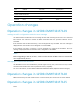
Figure 8 File transfer progress When the download is complete, the following information appears: Download successfully! 98844672 bytes downloaded! Input the File Name:update.ipe Updating File cfa0:/update.ipe.............................................. .....................................................
2. If you are using the console port for file transfer, check the HyperTerminal settings (including the baud rate and data bits) for any wrong setting. 3. Check the file transfer settings: If XMODEM is used, you must set the same baud rate for the terminal as for the console port. If TFTP is used, you must enter the same server IP addresses, file name, and working directory as set on the TFTP server.