Installation Guide ProCurve Series 8100fl Switches: Switch fl Modules www.procurve.
ProCurve Switch 8100fl Series: Switch fl Modules Installation Guide
© Copyright 2005 – 2007 Hewlett-Packard Development Company, L.P. The information contained herein is subject to change without notice. This document contains proprietary information, which is protected by copyright. No part of this document may be photocopied, reproduced, or translated into another language without the prior written consent of Hewlett-Packard.
Contents ProCurve Switch fl Modules . . . . . . . . . . . . . . . . . . . . . . . . . . . . . . . . . . . . 1 Interface Module Features . . . . . . . . . . . . . . . . . . . . . . . . . . . . . . . . . . . . . 5 Hot Swapping and Redundancy . . . . . . . . . . . . . . . . . . . . . . . . . . . . . . . . 6 Fail Over Protection . . . . . . . . . . . . . . . . . . . . . . . . . . . . . . . . . . . . . . . . . . 6 Configuration Changes to Management Module . . . . . . . . . . . . . . . . . . .
Mode Conditioning Patch Cord for Gigabit-LX . . . . . . . . . . . . . . . . . . 33 Installing the Patch Cord . . . . . . . . . . . . . . . . . . . . . . . . . . . . . . . . . . . . . 34 Specifications . . . . . . . . . . . . . . . . . . . . . . . . . . . . . . . . . . . . . . . . . . . . . . . . . 35 Environmental . . . . . . . . . . . . . . . . . . . . . . . . . . . . . . . . . . . . . . . . . . . . . 35 Lasers . . . . . . . . . . . . . . . . . . . . . . . . . . . . . . . . . . . . . . . . . . . . . . . .
ProCurve Switch fl Modules ProCurve Switch fl Modules For the ProCurve Switch 8100fl Series ProCurve Switch fl modules are components used in the ProCurve 8100fl Switch Series (Switch 8108fl and Switch 8116fl) to provide a variety of network connectivity options. Each module is shipped separately from the chassis. The different types of modules are described in this chapter.
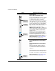
ProCurve Switch fl Modules Module Module Type and Description ProCurve Switch fl Redundant Management Module (J8731A) A ProCurve Switch 8100fl requires at least one primary management module to operate. You can install a second management module for redundancy. PCMCIA card slot (reserved for future use) 10/100 Base-T port (RJ-45) Active and Status LEDs The management module maintains persistent images of all software that runs on the system.
ProCurve Switch fl Modules Module Module Type and Description ProCurve Switch fl 1-Port GbE LR Interface Module (J8733A) Activity and Link LEDs LR port Long-reach (LR) LAN port. LR port with SC connector for 10 Gigabit operation over single-mode fiber optic cable. Activity, Link, and Status LEDs. See Table 3 on page 20 for information on interface module LEDs. This module was discontinued is Summer 2006.
ProCurve Switch fl Modules Module Activity and Link LEDs (per port) Ports 1-4 Ports 5-8 Module Type and Description ProCurve Switch fl 10-Port Mini-GBIC Interface Module (J8735A) Gigabit Ethernet ports. Ten 1-Gigabit Ethernet ports that use only the following supported mini-GBICs: • ProCurve Gigabit-SX LC mini-GBIC (J4858B) • ProCurve Gigabit-LX LC mini-GBIC (J4859B) • ProCurve Gigabit-LH LC mini-GBIC (J4860B) • ProCurve Gigabit 1000Base-T mini-GBIC (J8177B) Activity, Link, and Status LEDs.
ProCurve Switch fl Modules Module Module Type and Description ProCurve Switch fl 2-Port X2 10GbE Module (J8737A) Link and Activity LEDs Transceiver slot cover Transceiver slot. The X2 10GbE module supports the following transceivers (as of this printing)*: • 10 Gigabit-X2-SC SR Optic transceiver (J8436A) • 10 Gigabit-X2-SC LR Optic transceiver (J8437A) • 10 Gigabit-X2-SC ER Optic transceiver (J8438A) • 10 Gigabit-X2-CX4 Copper transceiver (J8440A) – 10 Gigabit-X2-CX4 Optical Media Converter (J8439A).
ProCurve Switch fl Modules • The ports on the Gigabit-SX and Gigabit-LX LC mini-GBICs installed in the10-Port Mini-GBIC Interface Module are compatible with IEEE 802.3z Gigabit-SX and Gigabit-LX standards, respectively. • The transceiver ports on the X2 10GbE Interface Modules (J8736A and J8737A) are compliant with X2 and XENPAK MSAs, and are compatible with the IEEE 802.3ak CX4 and IEEE 802.3ae XAUI industry standards.
ProCurve Switch fl Modules To perform a controlled shutdown on a management or fabric module, and cause the redundant module to take over, enter the following command: ProCurve 8100fl# halt You can also perform a controlled shutdown on a management or fabric module and cause the redundant module to take over, by entering the following command: ProCurve 8100fl# power down Note To display a list of the slot numbers of all installed modules, type ? after the command; for example, halt ? or po
ProCurve Switch fl Modules Installing Modules Installing Modules Installation procedures are similar for all modules. However, because there are three different types of modules—switch fabric, management, and interface modules—make sure that you insert each module in its appropriate slot. See the following sections for details.
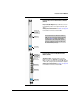
ProCurve Switch fl Modules Installing Modules Caution To avoid damaging modules and the backplane, be sure to insert each type of module in its appropriate slot by referring to the slot number or label, as shown in the following illustration. Numbered slots for interface modules FM slots for switch fabric modules MM slots for management modules 2. If you are using a 10-Port Mini-GBIC Interface Module, install the mini-GBICs in the module.
ProCurve Switch fl Modules Installing Modules Installation Precautions 5. Verify that network connections are working properly (see “Verifying Cable Connections” on page 20). 6. Configure the ports on any newly installed interface module (see “Customizing a Port Configuration” on page 24). ■ Avoid damage from static electricity. Static electricity can severely damage the electronic components on the modules.
ProCurve Switch fl Modules Installing Modules Installing a Switch Fabric Module A ProCurve Switch 8100fl requires at least one switch fabric module to process traffic for any interface module. Only one switch fabric module is required for full throughput. Note that the 8-slot Switch 8108fl uses the half-height switch fabric module. The 16-slot Switch 8116fl uses a full-height switch fabric module. These modules are not interchangeable.
ProCurve Switch fl Modules Installing Modules 6. Tighten the captive screw on each ejector by hand and seat with a screw driver to keep the module from being removed accidentally. Do not overtighten the captive screws. (You can tighten the thumb screws with a P2 Phillips screwdriver to eliminate the possibility of casual removal by unauthorized personnel.) 2. Install switch fabric modules in either of the two center slots. 3. Rotate ejectors to secure and tighten captive screws. 1.
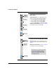
ProCurve Switch fl Modules Installing Modules Installing a Management Module The management module is the main processing unit of a ProCurve Switch 8100fl and is required for the switch to operate. The management module contains system-wide bridging and routing tables, and runs the main control protocols. You can install the same management module in both the Switch 8108fl and Switch 8116fl chassis.
ProCurve Switch fl Modules Installing Modules 6. Tighten the captive screw on each ejector by hand and seat with a screw driver to keep the module from being removed accidentally. Do not overtighten the captive screws. (You can tighten the thumb screws with a P2 Phillips screwdriver to eliminate the possibility of casual removal by unauthorized personnel.) 2. Install management modules on either side of the two central slots. 3. Push in ejectors in to secure and tighten captive screws. 1.
ProCurve Switch fl Modules Installing Modules Installing an Interface Module ProCurve 8100fl switches provide non-blocking throughput regardless of the software features you are using. Therefore, you do not need to “load balance” interface modules by placing them in certain physical relationships to balance the load on the backplane. Regardless of where you install the interface modules, the backplane can provide full, non-blocking throughput.
ProCurve Switch fl Modules Installing Modules 2. Install interface modules in any of the numbered slots on the left and right side of the chassis. 3. Push ejectors in to secure and tighten captive screws. 1. Pull out upper ejector lever and hold it in unlocked position. Interface Module Metal Plate Module Guides Note An interface module must be fully seated and the ejectors must be fully locked (vertical) before the captive screws will align properly.
ProCurve Switch fl Modules Installing Modules Verifying Module Installation After you have installed all the modules necessary for your switch, follow the procedure in this section verify correct module installation. To verify module installation: 1. Make sure all exposed interface module slots and power supply bays are free of foreign objects, such as tools, and have the correct slot covers. 2. Replace the power and slot covers over any empty power bays and module slots.
ProCurve Switch fl Modules Installing Modules Connecting the Network Cables After you verify the installation of each module and have installed the requisite mini-GBICs or transceivers, connect the appropriate network cable to each port according to the cable types defined in Table 1. For more information about cabling, see “Connectors and Cables” on page 35. Table 1.
ProCurve Switch fl Modules Installing Modules Module Port Type/ Transceiver Cable Type Length Limits 1-Port 10-GbE Interface Module (J8733A) 10-Gbe LR 9/125 μm (core-cladding) diameter, 1310 nm, low metal content, single-mode fiber optic cables fitted with SC connectors. The cables must comply with the ITU-T G.651 and ISO/ IEC 793-2 Type A1b or A1a standards. 10 kilometers (single-mode cable) X2 10GbE Modules (J8736A/J8737A) 10-GbE SR Multimode fiber-optic cable designed for Gigabit Ethernet: 62.
ProCurve Switch fl Modules Installing Modules Verifying Cable Connections For Switch fl interface modules, when you connect a network cable from an active network device to the switch, the LED for the switch port should light on as described in Table 2 and Table 3. Management and Switch Fabric Modules LEDs The ProCurve Switch fl Redundant Management and Switch Fabric Modules have an Active LED (on top) and a Status LED (on bottom). The LED states described in Table 2 are common to both types of module.
ProCurve Switch fl Modules Installing Modules 1-Port 10GB LR Module (J8733A) (Continued) LED Color State Meaning Link Green Solid Link is up. n/a Off No connector is plugged into the port. n/a Off No power is reaching the module. Green Flashing Module is powering up and downloading operating software. Green Solid Software image loaded successfully. Yellow/ Orange Flashing Self-test failure.
ProCurve Switch fl Modules Installing Modules LED Color State Meaning 10-Port mini-GBIC Module (J8735A) (Continued) Status n/a Off No power is reaching the module. Green Flashing LED is solid green to flashing green during boot up. Solid green indicates that the module is loading the system image. Green Solid Software image loaded successfully. Orange Flashing Self-test failure. X2 10GbE Interface Modules (J8736A and J8737A) Link Green Solid Link is up.
ProCurve Switch fl Modules Installing Modules Troubleshooting Module Operation If the Link LED for a port does not light on, follow the procedures in Table 4 to troubleshoot the module operation. Table 4. Using LEDs to Troubleshoot Error Condition Diagnostic Procedure A port LED remains off after • Verify that both ends of the port’s cabling (at the switch and at the connected device) are securely connected. you connect a cable.
ProCurve Switch fl Modules Installing Modules Customizing a Port Configuration The ProCurve Switch 8100fl allows you to build a configuration for a module that is not yet installed. For example, although slot 2 is empty, you can still configure an interface, add an IP address to it, and then save the configuration for later use. If the slot in which you install a module has not been preconfigured, you must configure the module and enable its ports for network operation.
ProCurve Switch fl Modules Installing or Removing Transceivers Installing or Removing Transceivers If you installed an X2 10GbE module (J8736A or J8737A), you can now install a copper or fiber optic transceiver to enable network connectivity to the port. Note You can install or remove a transceiver without having to power off the switch. Use only the ProCurve supported transceivers (see page 5). Installing Transceivers To install a transceiver: 1.
ProCurve Switch fl Modules Installing or Removing Transceivers Removing Transceivers To remove a transceiver: 1. Disconnect the network cable from the transceiver before removing it from the module. 2. If your transceiver has a wire bail, lower the bail and then use the bail to pull the transceiver from the slot. If your transceiver does not have a bail, pull the transceiver straight out.
ProCurve Switch fl Modules Installing and Removing mini-GBICs Installing and Removing mini-GBICs You can remove or install a mini-GBIC from the 10-port mini-GBIC Module without having to power off the switch. Use only ProCurve mini-GBICs.
ProCurve Switch fl Modules Installing and Removing mini-GBICs Caution If the mini-GBIC does not go in easily, do not force it. If it is not oriented properly, it will stop about one quarter of the way into the slot—remove and reorient the mini-GBIC so that it slides easily into the slot. Keep the dust plug in the mini-GBIC when no fiber cable is plugged in. The optics will not work properly when obstructed with dust or contaminants.
ProCurve Switch fl Modules Installing and Removing mini-GBICs mini-GBIC with plastic tab or collar Locking tab releases from socket Remove ProCurve mini-GBIC Release ProCurve mini-GBIC ProCurve mini-GBIC Installed Position Locking tab Socket Release tab 1. Pull release tab in to unlatch 2. Remove from socket 3. Pull the mini-GBIC out of the slot. 4. If the device is not defective (disposable), insert a dust plug to protect it.
ProCurve Switch fl Modules Installing and Removing mini-GBICs To remove a mini-GBICs with a wire bail: 1. Remove the fiber cable from the mini-GBIC. 2. Lower the bail until it is approximately horizontal. mini-GBIC with wire bail release Socket Installed Position ProCurve mini-GBIC Bail Locking tab Locking tab releases from socket Release ProCurve mini-GBIC 1. Pull bail out to unlatch 2. Remove from socket Remove ProCurve mini-GBIC 30 3. Using the bail, pull the mini-GBIC out of the slot. 4.
ProCurve Switch fl Modules Replacing or Removing a Module Replacing or Removing a Module Follow the procedures in this section to replace an installed module with a new module, or to remove a module without replacing it. When installing a new module, it is not necessary to reset the switch. However, some configuration changes may be required for the module to be made operational. See below for details. Caution Be careful when you remove an interface module from the switch.
ProCurve Switch fl Modules Troubleshooting and Support Troubleshooting and Support One of the main ways to troubleshoot the operation of Switch fl modules is by using the LEDs on the front of the switch and on the modules. Refer to the tables in “Verifying Cable Connections” on page 20 for a description of normal LED behavior. Also, refer to the ProCurve Switch 8100fl Series: Installation and Getting Started Guide for more detailed troubleshooting information.
ProCurve Switch fl Modules Mode Conditioning Patch Cord for Gigabit-LX Mode Conditioning Patch Cord for Gigabit-LX The following information applies to installations in which multimode fiber-optic cables are connected to a Gigabit-LX port. Unlike Gigabit-SX, which connects to only multimode fiber-optic cabling, Gigabit-LX can use either single-mode or multimode cable.
ProCurve Switch fl Modules Mode Conditioning Patch Cord for Gigabit-LX Installing the Patch Cord As shown in the illustration below, connect the patch cord to the Gigabit-LX mini-GBIC with the section of single-mode fiber plugged in to the Tx (transmit) port. Then, connect the other end of the patch cord to your network cabling patch panel, or directly to the network multimode fiber.
ProCurve Switch fl Modules Specifications Specifications Environmental Operating Non-Operating Temperature: 5°C to 40°C (41°F to 104°F) -40°C to 70°C (-40°F to 158°F) Relative humidity: (non-condensing) 15% to 80% (@40°C, 24 hours) 90% (@ 65°C, 12 hours) Maximum altitude: 3.0 Km (10,000 ft) 4.6 Km (15,000 ft) Lasers The Gigabit-SX, Gigabit-LX, and Gigabit-LH mini-GBICs, which can be installed in the 10-Port mini-GBIC Module, are Class 1 Laser Products. Laser Klasse 1.
ProCurve Switch fl Modules Specifications Table 5. Twisted-Pair Cables Port Type Cable Specifications Maximum Length 10 Mbps Operation Category 3, 4, or 5 100-ohm balanced unshielded twisted-pair (UTP) or shielded twisted-pair (STP) cable, complying with IEEE 802.3 10Base-T specifications, fitted with RJ-45 connectors 100 meters 100 Mbps Operation Category 5 100-ohm balanced UTP or STP cable, complying with IEEE 802.
ProCurve Switch fl Modules Specifications Fiber-Optic ■ Gigabit-SX LC connectors on the Gigabit-SX mini-GBIC (used on the 10 Port Mini-GBIC Interface Module) transmit at 850 nm wavelength, and are compatible with the IEEE 802.3z Gigabit-SX standard. These connectors accepts the low metal content, multimode fiber-optic cables for GigabitSX described in Table 6.
ProCurve Switch fl Modules Specifications Port Type Cable Specifications Connector Type Multimode fiber-optic cable designed for Gigabit Ethernet: 62.5/125 μm (core/cladding) diameter or 50/ 125 μm, 850 nm, low metal content, complying with the ITU-T G.652 and ISO/IEC 793-2 Type B1 standards. SC Multimode fiber-optic cable designed for Gigabit Ethernet: 62.5/125 μm (core/cladding) diameter or 50/ 125 μm, 850 nm, low metal content, complying with the ITU-T G.652 and ISO/IEC 793-2 Type B1 standards.
ProCurve Switch fl Modules EMC Regulatory Statements EMC Regulatory Statements U.S.A. FCC Class A This equipment has been tested and found to comply with the limits for a Class A digital device, pursuant to Part 15 of the FCC Rules. These limits are designed to provide reasonable protection against interference when the equipment is operated in a commercial environment.
ProCurve Switch fl Modules EMC Regulatory Statements Korea Taiwan European Community Declaration of Conformity These products are designed for operation with the ProCurve Switch 8100fl Series. Please see the Declarations of Conformity included in the ProCurve Switch 8100fl Series: Installation and Getting Started Guide.
— This page is intentionally unused.
Technical information in this document is subject to change without notice. © Copyright Hewlett-Packard Company 2005–2007. All rights reserved. Reproduction, adaptation, or translation without prior written permission is prohibited except as allowed under the copyright laws.