
3Com Switch 8800 Advanced Software V5 Configuration Guide


100 CHAPTER 11: MSTP CONFIGURATION
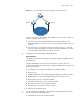
Switch C ■ Port CP1 receives a configuration BPDU
from Switch A (that is, {0, 0, 0, AP2}).
As the received configuration BPDU is
superior to that of the local port (that
is, {2, 0, 2, CP1}), Switch C uses the
received configuration BPDU as the
configuration BPDU of CP1.
■ Port CP2 receives a configuration BPDU
from Switch B (that is, {1, 0, 1, BP2})
before the configuration BPDU is
updated on BP2. As the received
configuration BPDU is superior to that
of the local port (that is, {2, 0, 2, CP2}),
Switch C uses the received
configuration BPDU as the
configuration BPDU of CP2.
CP1: {0, 0, 0, AP2}
CP2: {1, 0, 1, BP2}
By comparison:
■ The configuration BPDUs of CP1 is the
optimum configuration BPDU, so CP1
acts as the root port, the configuration
BPDUs of which remains unchanged.
■ Switch C generates a designated port
configuration BPDU (that is, {0, 10, 2,
CP2}) and compare it with the
configuration BPDU of CP2. As the
former is superior, CP2 acts as a
designated port and Switch C sends
the generated configuration BPDU
through CP2 periodically.
Root port CP1:
{0, 0, 0, AP2}
Designated port CP2:
{0, 10, 2, CP2}
■ Next, port CP2 receives the updated
configuration BPDU of Switch B (that
is, {0, 5, 1, BP2}). As the received
configuration BPDU is superior to the
local one, Switch C launches a BPDU
update process.
■ At the same time, port CP1 receives
configuration BPDUs periodically from
Switch A. Switch C does not launch an
update process after comparison.
CP1: {0, 0, 0, AP2}
CP2: {0, 5, 1, BP2}
By comparison:
■ Because the root path cost of CP2 (
which is 9) is smaller than the root
path cost of CP1 (which is 10), the
configuration BPDU of CP2 is the
optimum BPDU, and CP2 acts as the
root port, the configuration BPDUs of
which remains unchanged.
■ After the comparison between the
configuration BPDU of CP1 and the
generated designated port
configuration BPDU, port CP1 is
blocked, with the configuration BPDU
of the port remaining unchanged, and
the port will not receive data from
Switch A until a spanning tree
computing process is triggered by a
new condition, for example, the link
between Switch B and Switch C
becomes down.
Blocked port CP1:
{0, 0, 0, AP2}
Root port CP2:
{0, 5, 1, BP2}
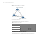
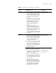
Table 12 Comparison process and result on each device
Device Comparison process
BPDU of the port after
comparison