
3Com Switch 8800 Advanced Software V5 Configuration Guide


PoE Configuration Example 1019
The display commands are available in any view.
PoE Configuration
Example
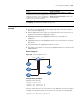
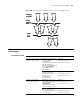
Network requirements
■ The device is equipped with two PoE-supporting cards, which are inserted in
slot 3 and slot 5 respectively.
■ Allocate 400 watts to the card in slot 3 and full power to the card in slot 5 to
guarantee normal power supplying to all PSEs.
■ GigabitEthernet3/1/1 and GigabitEthernet3/1/2 are connected to IP
telephones.
■ GigabitEthernet5/1/1 and GigabitEthernet5/1/2 are connected to access point
(AP) devices.
■ The power priority of GigabitEthernet3/1/2 is critical.
■ The power of the AP device connected to GigabitEthernet5/1/1 cannot exceed
9,000 milliwatts.
Network diagram
Figure 303 Network diagram for PoE
Configuration procedure
# Enable PoE for the PSE.
<Sysname> system-view
[Sysname] poe enable pse 10
[Sysname] poe enable pse 16
# Set the maximum power for the card in slot 3 to 400 watts. You do not need to
configure the maximum power for the card in slot 5 because it is full by default.
[Sysname] poe max-power 400 pse 10
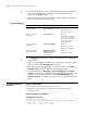
Display all information of the configurations
and applications of the PoE configuration file
display poe-profile [ index index | name
profile-name ]
Display all information of the configurations
and applications of the PoE configuration file
applied to the specified PoE interface
display poe-profile interface interface-type
interface-number
To do... Use the command...
GE3/1
GE3/2
GE5/1
GE5/1