
3Com Switch 8800 Advanced Software V5 Configuration Guide


1024 CHAPTER 79: SYSTEM MAINTENANCE AND DEBUGGING
The tracert command
By using the tracert command, you can trace the switches involved in delivering a
packet from source to destination. This is useful for identification of failed node(s)
in the event of network failure.
The tracert command involves the following steps in its execution:
1 The source device sends a packet with a TTL value of 1 to the destination device.
2 The first hop (the switch that first receives the packet; the value of TTL decreases
by 1 by each hop) responds by sending a TTL-expired ICMP message to the source,
with its IP address encapsulated. In this way, the source device can get the address
of the first switch.
3 The source device sends a packet with a TTL value of 2 to the destination device.
4 The second hop responds with a TTL-expired ICMP message, which gives the
source device the address of the second switch.
5 The above process continues until the ultimate destination device is reached. In
this way, the source device can trace the addresses of all the switches that a
packet traverses from the source device to the destination device.
Introduction to System
Debugging
For the majority of protocols and new features provided, the system provides
corresponding debugging functions to help users diagnose errors.
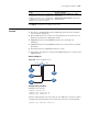
The following two switches control the display of debugging information:
■ Protocol debugging switch, which controls the output of protocol-specific
debugging information
■ Screen output switch, which controls whether to display the debugging
information on a certain screen.
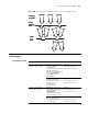
Figure 304 illustrates the relationship between the protocol debugging switch and
the screen output switch. Only when both are turned on can debugging
information be output on a terminal.