
3Com Switch 8800 Advanced Software V5 Configuration Guide

NTP Configuration Examples 1085
Configuring NTP
Broadcast Mode with
Authentication
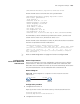
Network requirements
Switch C’s local clock is to be used as a reference source, with the stratum level of
2, and Switch C sends out broadcast messages from VLAN-interface 2. Switch D is
to receive broadcast client through VLAN-interface 2, with NTP authentication
enabled on both the server and client.
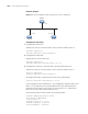
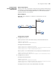
Network diagram
Figure 319 Network diagram for configuration of NTP broadcast mode with
authentication
Configuration procedure
1 Configuration on Switch C:
# Specify the local clock as the reference source, with the stratum level of 3.
<SwitchC> system-view
[SwitchC] ntp-service refclock-master 3
# Configure NTP authentication
[SwitchC] ntp-service authentication enable
[SwitchC] ntp-service authentication-keyid 88 authentication-mode md5 123456
[SwitchC] ntp-service reliable authentication-keyid 88
# Specify Switch C as an NTP broadcast server, and specify an authentication ID.
[SwitchC] interface vlan-interface 2
[SwitchC-Vlan-interface2] ntp-service broadcast-server authentication-id 88
2 Configuration on Switch D:
# Configure NTP authentication
<SwitchD> system-view
[SwitchD] ntp-service authentication enable
[SwitchD] ntp-service authentication-keyid 88 authentication-mode md5 123456
[SwitchD] ntp-service reliable authentication-keyid 88
# Configure Switch D to work in the NTP broadcast client mode
Vlan-int3
1.0.1.11/24
Vlan-int3
1.0.1 .10/24
Vlan-int2
3.0.1.31/24
Vlan-int2
3.0.1.32/24
Vlan-int2
3.0.1.30/24
Switch A Switch B
Switch C
Switch D