
3Com Switch 8800 Advanced Software V5 Configuration Guide
1086 CHAPTER 85: NTP CONFIGURATION
[SwitchD] interface vlan-interface 2
[SwitchD-Vlan-interface2] ntp-service broadcast-client
Now, Switch D can receive broadcast messages through VLAN-interface 2, and
Switch C can send broadcast messages through VLAN-interface 2. Upon receiving
a broadcast message from Switch C, Switch D synchronizes its clock with that of
Switch C.
# View the NTP status of Switch D after clock synchronization.
[SwitchD] display ntp-service status
Clock status: synchronized
Clock stratum: 4
Reference clock ID: 3.0.1.31
Nominal frequency: 64.0000 Hz
Actual frequency: 64.0000 Hz
Clock precision: 2^7
Clock offset: 0.0000 ms
Root delay: 31.00 ms
Root dispersion: 8.31 ms
Peer dispersion: 34.30 ms
Reference time: 16:01:51.713 UTC Sep 19 2005 (C6D95F6F.B6872B02)
As shown above, Switch D has been synchronized to Device C, and the clock
stratum level of Switch D is 4, while that of Switch C is 3.
# View the NTP session information of Switch D, which shows that an association
has been set up between Switch D and Switch C.
[SwitchD] display ntp-service sessions
source reference stra reach poll now offset delay disper
**************************************************************************
[1234] 3.0.1.31 127.127.1.0 3 254 64 62 -16.0 32.0 16.6
note: 1 source(master),2 source(peer),3 selected,4 candidate,5 configured
Total associations : 1
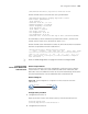
Configuring MPLS VPN
Time Synchronization in
Server/Client Mode
Network requirements
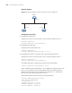
As shown in Figure 320, two VPNs are present on PE 1 and PE 2: VPN 1 and VPN
2. CE 1 and CE 2 are devices in VPN 1, while CE 3 and CE 4 are devices in VPN 2.
It is required that CE 2 can be synchronized to CE 1 in the server/client mode. CE 1
is synchronized to the local reference source, with the clock stratum level being 1.
n
At present, MPLS VPN time synchronization can be implemented only in the
unicast mode (server/client mode or symmetric peers mode), but not in the
multicast or broadcast mode.