
3Com Switch 8800 Advanced Software V5 Configuration Guide

NTP Configuration Examples 1087
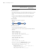
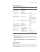
Network diagram
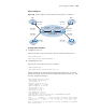
Figure 320 Network diagram for MPLS VPN time synchronization configuration
Configuration procedure
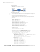
1 Configuration on CE 1:
# Specify the local clock as the reference source, with the stratum level of 1.
<CE1> system-view
[CE1] ntp-service refclcok-master 1
2 Configuration on CE 2:
# Specify CE 1 as the NTP server of CE 2 in VPN 1.
<CE2> system-view
[CE2] ntp-service unicast-server 10.1.1.1
# View the NTP session information and status information on CE 2 a certain
period of time later. You can see that CE 2 has been synchronized to CE 1, with
the clock stratum level being 2.
[CE2] display ntp-service status
Clock status: synchronized
Clock stratum: 2
Reference clock ID: 10.1.1.1
Nominal frequency: 63.9100 Hz
Actual frequency: 63.9100 Hz
Clock precision: 2^7
Clock offset: 0.0000 ms
Root delay: 47.00 ms
Root dispersion: 0.18 ms
Peer dispersion: 34.29 ms
Reference time: 02:36:23.119 UTC Jan 1 2001(BDFA6BA7.1E76C8B4)
[CE2] display ntp-service sessions
source reference stra reach poll now offset delay disper
**************************************************************************
[12345]10.1.1.1 LOCL 1 7 64 15 0.0 47.0 7.8
note: 1 source(master),2 source(peer),3 selected,4 candidate,5 configured
Total associations : 1
CE 1
CE 3 CE 4
CE 2
PE 1 PE 2P
VPN 1
VPN 2
VPN 1
VPN 2
Vlan-int20
MPLS backbone
10. 1. 1.1 /24
Vlan-int20
10 .3 .1. 1/ 24
Vlan-int20 Vlan-int20
10. 2.1 .1/ 24 10 .4 .1.1/ 24
Vlan-int20
10.1.1 .2/24
Vlan-int20
10.3.1.2/24
Vlan-int20
172.1.1.2/24
Vlan-int21
172.2.1 .1/24
Vlan-int21 Vlan-int21
172.1.1.1/24 172 .2.1.2/24
Vlan-int22
10. 2.1 .2/ 24
Vlan-int22
10 .4 .1. 2/ 24