
3Com Switch 8800 Advanced Software V5 Configuration Guide

126 CHAPTER 11: MSTP CONFIGURATION
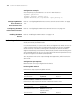
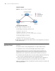
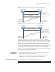
■ Ethernet 1/1/1 on Switch A and Ethernet 1/1/2 on Switch B allow VLAN 1 to
pass. Ethernet 1/1/3 on Switch A and Ethernet 1/1/4 on Switch B allow VLAN 2
to pass.
■ Switch A is the root bridge, and both Switch A and Switch B run MSTP.
Ethernet 1/1/4 on Switch B is blocked, causing traffic block on VLAN 2.
■ Configure VLAN Ignore to keep the ports in VLAN 2 on Switch B in the
forwarding state.
Network diagram
Figure 31 VLAN Ignore configuration
Configuration procedure
1 Enable VLAN Ignore on Switch B.
# Enable VLAN Ignore on VLAN 2.
<SysnameB> system-view
[SysnameB] stp ignored vlan 2
2 Verify the configuration
# Display the VLAN Ignore-enabled VLANs.
[SysnameB] display stp ignored-vlan
STP-Ignored VLAN: 2
Configuring Digest
Snooping
As defined in IEEE 802.1s, interconnected devices are in the same region only
when the region related configuration (domain name, revision level,
VLAN-to-instance mappings) on them is identical. An MSTP enabled device
identifies devices in the same MST region via checking the configuration ID in
BPDU packets. The configuration ID includes the region name, revision level,
configuration digest that is in 16-byte length and is the result computed via the
HMAC-MD5 algorithm based on VLAN-to-instance mappings.
In practical networking implementations, since MSTP implementations differ with
vendors, the configuration digest computed using private keys is different; hence
different vendors’ devices in the same MST region can not communicate with each
other.
Enabling the Digest Snooping feature on the associated port can make a device
communicate with another vendor’s device in the same MST region.
Configuration
Prerequisites
Associated devices of different vendors are interconnected and run MSTP.
Eth1/1/1
Switch A Switch B
VLAN 1
VLAN 2
Eth1/1/3 Eth1/1/4
Eth1/1/2