
3Com Switch 8800 Advanced Software V5 Configuration Guide


MSTP Configuration Examples 135
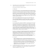
Network diagram
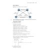
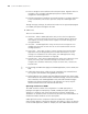
Figure 36 Network diagram for MSTP configuration
n
"Permit:" beside each link in the figure is followed by the VLANs the packets of
which are permitted to pass this link.
Configuration procedure
1 Configuration on Switch A
# Configure an MST region.
<SysnameA> system-view
[SysnameA] stp region-configuration
[SysnameA-mst-region] region-name example
[SysnameA-mst-region] instance 1 vlan 10
[SysnameA-mst-region] instance 3 vlan 30
[SysnameA-mst-region] instance 4 vlan 40
[SysnameA-mst-region] revision-level 0
# Activate MST region configuration manually.
[SysnameA-mst-region] active region-configuration
[SysnameA-mst-region] quit
# Configure Switch A as the root bridge of MST instance 1.
[SysnameA] stp instance 1 root primary
# View the MST region configuration information that has taken effect.
[SysnameA] display stp region-configuration
Oper configuration
Format selector :0
Region name :example
Revision level :0
Instance Vlans Mapped
0 1 to 9, 11 to 29, 31 to 39, 41 to 4094
1 10
3 30
4 40
2 Configuration on Switch B
# Configure an MST region.