
3Com Switch 8800 Advanced Software V5 Configuration Guide


13
BPDU TUNNELING CONFIGURATION
When configuring BPDU tunneling, refer to the following sections:
■ “Introduction to BPDU Tunneling” on page 149
■ “Configuring BPDU Isolation” on page 150
■ “Configuring BPDU Transparent Transmission” on page 151
■ “BPDU Tunneling Configuration Example” on page 152
Introduction to BPDU
Tunneling
Why BPDU Tunneling To avoid loops in your network, you can enable the spanning tree protocol (STP)
on your device. However, STP gets aware of the topological structure of a network
by means of bridge protocol data units (BPDUs) exchanged between different
devices and the BPDUs are Layer 2 multicast packets, which can be received and
processed by all STP-enabled devices on the network. This prevents each network
from correctly calculating its spanning tree. As a result, when redundant links exist
in a network, data loops will unavoidably occur.
By allowing each network has its own spanning tree while running STP, BPDU
tunneling can resolve this problem. It has the following functions:
■ It can isolate BPDUs of different customer networks, so that one network is not
affected by others while calculating the topological structure.
■ It enables BPDUs of the same customer network to be multicast over specific
VLAN VPNs in the service provider network, so that the same, geographically
dispersed customer network can implement consistent spanning tree
calculation across the service provider network.
n
BPDU tunneling for the Switch 8800 Family only supports STP packets.
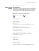
How BPDU Tunneling
Works
The BPDU tunneling works implements the following two functions:
■ BPDU isolation
■ BPDU transparent transmission
The work process of IGMP is as follows: