
3Com Switch 8800 Advanced Software V5 Configuration Guide


152 CHAPTER 13: BPDU TUNNELING CONFIGURATION
■ The BPDU tunneling feature is incompatible with the GVRP feature, so these
two features cannot be enabled at the same time. For introduction to GVRP,
refer to
“GVRP Configuration” on page 139.
BPDU Tunneling
Configuration
Example
Network requirements
■ Customer A, Customer B, Customer C, and Customer D are customer network
access devices.
■ Provider A, Provider B, and Provider C are service provider network access
devices, which are interconnected through configured trunk ports.
The configuration is required to satisfy the following requirements:
■ Geographically dispersed customer networks Customer A, Customer C and
Customer D can implement consistent spanning tree calculation across the
service provider network.
■ BPDU packets are isolated for the customer network Customer B, so it does not
take part in the spanning tree calculation.
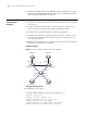
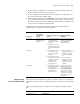
Network diagram
Figure 42 Network diagram for BPDU tunneling configuration
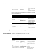
Configuration procedure
1 Configuration on Provider A
# Configure BPDU transparent transmission on Ethernet 1/1/1.
<Sysname> system-view
[Sysname] interface ethernet 1/1/1
[Sysname-Ethernet1/1/1] port access vlan 2
[Sysname-Ethernet1/1/1] stp disable
[Sysname-Ethernet1/1/1] bpdu-tunnel dot1q enable
[Sysname-Ethernet1/1/1] bpdu-tunnel dot1q stp
Eth1/1/1 Eth1/1/2
VLAN 2 VLAN 4
VLAN 2VLAN 2
Eth1/1 /3Eth1 /1/4
Trunk Trunk
Trunk
Customer B
Customer A
Customer D Customer C
Provider B
Provider A
Provider C