
3Com Switch 8800 Advanced Software V5 Configuration Guide


164 CHAPTER 14: VLAN CONFIGURATION
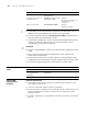
■ The default VLAN ID of the Trunk port is 100;
■ The Trunk port allows packets from VLAN 2, VLAN 6 through VLAN 50, and
VLAN 100 to pass.
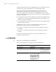
Network diagram
Figure 46 Network diagram for port-based VLAN configuration
Configuration procedure
Configure Switch A:
# Create VLAN 100.
<SysnameA> system-view
[SysnameA] vlan 100
[SysnameA-vlan100] quit
# Enter Ethernet interface view of Ethernet 1/1/1.
[SysnameA] interface ethernet 1/1/1
# Configure Ethernet 1/1/1 as a Trunk port and configure its default VLAN ID as
100.
[SysnameA-Ethernet1/1/1] port link-type trunk
[SysnameA-Ethernet1/1/1] port trunk pvid vlan 100
# Configure Ethernet 1/1/1 to permit packets from VLAN 2, VLAN 6 through VLAN
50, and VLAN 100 to pass.
[SysnameA-Ethernet1/1/1] port trunk permit vlan 2 6 to 50 100
Configuration on Switch B is the same as that on Switch A.
Protocol-Based VLAN
Configuration Example
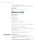
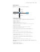
Network requirements
■ Switch A connects to Switch B through Hybrid port Ethernet 1/1/1, and
accesses to an IP network through port Ethernet 1/1/2.
■ Switch B is a common switch, which connect with multiple hosts for different
applications.
■ Through protocol-based VLAN configuration, make Ethernet 1/1/1 to forward
the received IPv4 packets to VLAN 2, and IPv6 packets to VLAN 6.
Et h1/1 /1
Eth1/1 /1
Switch A Switch B