
3Com Switch 8800 Advanced Software V5 Configuration Guide


168 CHAPTER 15: SUPER VLAN CONFIGURATION
n
■ The IP address of the VLAN interface configured in the above table is the IP
address of the corresponding VLAN interface of the super VLAN.
■ For more information about the local-proxy-arp enable command, refer to
the Switch 8800 Command Reference Guide.
■ A VLAN that is configured as a super VLAN cannot be configured as the Guest
VLAN for a certain port, and vice versa. For more information, refer to
“Configuring a Guest VLAN” on page 928.
c
CAUTION:
■ If a port is already added to a VLAN, the VLAN cannot be configured as a super
VLAN.
■ Layer 2 multicast function can be configured for a super VLAN, but the
function does not take effect.
■ The functions of DHCP, Layer 3 multicast, dynamic routing, and NAT can be
configured on the VLAN interface of a super VLAN, but only DHCP takes effect.
■ You cannot configure VRRP on the VLAN interface of a super VLAN.
Displaying Super
VLAN
Super VLAN
Configuration
Example
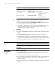
Network requirements
■ Create super VLAN 10, and configure the VLAN interface IP address of the
super VLAN as 10.0.0.1/24.
■ Create the sub-VLANs: VLAN 2, VLAN 3, and VLAN 5.
■ Ports Ethernet 0/1/1 and Ethernet 0/1/2 belong to VLAN 2, Ethernet 0/1/3 and
Ethernet 0/1/4 belong to VLAN 3, and Ethernet 0/1/5 and Ethernet 0/1/6
belong to VLAN 5.
■ Through configuration, the sub-VLANs are isolated at Layer 2 but connected at
Layer 3.
Enter VLAN interface view interface vlan-interface
vlan-interface-id
-
Configure the IP address of
the VLAN interface
ip address ip-address { mask |
mask-length } [ sub ]
Required
By default, the IP address of a
VLAN interface is not
configured
Enable local proxy ARP local-proxy-arp enable Required
Disabled by default
To do... Use the command... Remarks
To do... Use the command... Remarks
Display the mapping between
a super VLAN and its
sub-VLAN(s)
display supervlan [
supervlan-id ]
Available in any view