
3Com Switch 8800 Advanced Software V5 Configuration Guide


16
ISOLATE-USER VLAN
CONFIGURATION
When configuring Isolate-user VLAN, go to these sections for information you are
interested in:
■ “Introduction to Isolate-User-VLAN” on page 171
■ “Configuring Isolate-User-VLAN” on page 172
■ “Displaying and Maintaining Isolate-User-VLAN” on page 173
■ “Isolate-User-VLAN Configuration Example” on page 173
Introduction to
Isolate-User-VLAN
The isolate-user-VLAN adopts a two-tier VLAN structure. In this approach, two
types of VLANs, isolate-user-VLAN and secondary VLAN, are configured on the
same device.
■ The isolate-user-VLAN is mainly used for upstream data exchange. An
isolate-user-VLAN can have multiple secondary VLANs associated to it. The
upstream device only knows the isolate-user-VLAN, how the secondary VLANs
are working is not its concern. In this way, network configurations are
simplified and VLAN resources are saved.
■ Secondary VLANs are used for connecting users. Secondary VLANs are isolated
from each other on Layer 2.
■ One isolate-user-VLAN can have multiple secondary VLANs, which are invisible
to the corresponding upstream device.
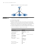
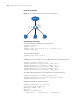
As illustrated in Figure 49, the isolate-user-VLAN function is enabled on Switch B.
VLAN 10 is the isolate-user-VLAN, and VLAN 2, VLAN 5, and VLAN 8 are
secondary VLANs that are mapped to VLAN 10 and invisible to Switch A. To realize
the Layer 3 connectivity between the secondary VLANs (VLAN 2, VLAN 5, and
VLAN 8) that are under the same isolate-user-VLAN (VLAN 10), the following two
methods can be used:
■ Configure a VLAN interface and the VLAN interface IP address for each
secondary VLAN on Switch B.
■ Configure the local proxy ARP function on the upper layer device (Switch A).
For detailed information about proxy ARP, refer to
“Proxy ARP Configuration”
on page 201.